ULN2003A Pinout Guide — 7-Ch Darlington Array, 500mA/50V
ULN2003A Pinout Guide - 7-Ch Darlington Array, 500mA/50V | ICMASS
The ULN2003A packs seven NPN Darlington pairs into a DIP-16 or SOIC-16. Each channel sinks 500mA at up to 50V, driven directly from 3.3V or 5V logic with no external resistors. Internal 2.7kΩ base resistors and flyback diodes on every output - the simplest one-chip bridge between a microcontroller and relays, motors, or solenoids.
Pin 9 (COM) is the most misunderstood pin on the datasheet. Leave it floating with an inductive load and you've just disabled every flyback diode on the chip. More on that below.
ULN2003A Pinout and Pin Functions
| Pin | Name | Type | Description |
|---|---|---|---|
| 1–7 | 1B–7B | Input | Darlington base inputs. Internal 2.7kΩ series resistor. Drive directly from 3.3V/5V GPIO. HIGH = output ON (sinking). |
| 8 | GND (E) | Ground | Common emitter for all 7 channels. Tie to system ground with a thick trace. |
| 9 | COM | Clamp | Common cathode for internal flyback diodes. For inductive loads, tie to the load supply rail (e.g., +12V). For resistive loads only, can float. |
| 10–16 | 7C–1C | Output | Open-collector outputs. Sink current when corresponding input is HIGH. 500mA/ch continuous, 50V max. |
Key Specifications
| Parameter | Value |
|---|---|
| Channels | 7 Darlington pairs |
| Output Voltage (max) | 50V |
| Collector Current (continuous) | 500mA per channel |
| Peak Collector Current | 600mA (pulsed) |
| Input Voltage (max) | 30V |
| Input Resistor (internal) | 2.7kΩ series base resistor per channel |
| VCE(sat) at 200mA | 0.95–1.3V |
| VCE(sat) at 350mA | 1.1–1.6V |
| DC Current Gain (hFE) | ~1000 at 350mA |
| Input Threshold (ON) | ~2.0–2.8V at 200–400mA load |
| Clamp Diode VF | 1.5–2.0V at 350mA |
| Turn-On / Turn-Off Delay | 0.25–1.0µs |
| Package | DIP-16 (through-hole) or SOIC-16 (SMD) |
| Operating Temperature | −40°C to +85°C |
Typical Application Circuit: Relay Driver
PCB Layout Tips
1. Separate logic and power sides. Inputs on the left (pins 1–7), outputs on the right (pins 10–16). Run MCU signals along the left edge and high-current traces along the right. Don't route them through the same area.
2. Thick traces on outputs, thin on inputs. Input traces carry ~1mA - 0.25mm (10mil) is plenty. Output traces may carry 500mA - use 0.5mm (20mil) minimum for single channels, 1mm (40mil) if paralleling outputs.
3. COM pin is not optional for inductive loads. Run a dedicated trace from pin 9 to the load supply rail, sized same as output traces. Without it, every inductive turn-off sends a voltage spike across the output transistor - not the clamp diode.
4. Ground plane or thick ground trace. All 7 channels return through pin 8 (GND). At 500mA × 4 channels, that's 2A through one pin. A solid ground plane under the IC is ideal. If using two-layer, make the GND trace at least 1.5mm wide.
5. Thermal: know your package. At 85°C, DIP-16 dissipates ~0.76W safely; SOIC-16 only ~0.33W. At VCE(sat) ≈ 1.3V/350mA, one channel at full load is 0.46W. Two channels at 350mA exceed SOIC-16 limits. Add copper pour, or switch to DIP-16 for high-current multi-channel.
Common Mistakes
| # | Mistake | What Happens | Fix |
|---|---|---|---|
| 1 | COM pin left floating with inductive load | Flyback voltage spike destroys the output transistor. The internal clamp diodes have no path to the supply rail. | Tie COM (pin 9) to the load supply rail (e.g., +12V). Always. |
| 2 | Exceeding total power dissipation | Junction temperature exceeds 125°C. SOIC-16 fails first - plastic package, smaller die pad. | Calculate PD = Σ(VCE(sat) × IC) per channel. Stay under 0.76W (DIP) or 0.33W (SOIC) at 85°C. |
| 3 | GPIO float at MCU startup | ULN2003A inputs float HIGH during MCU boot → all relays/loads briefly energise. Can cause dangerous unintended motion. | Add 4.7–10kΩ pull-down resistors from each input to GND. |
| 4 | Driving from 3.3V MCU without checking threshold | ULN2003A input threshold is ~2.0–2.8V depending on load. 3.3V GPIO may be marginal at 400mA+ loads. | Works fine for loads ≤300mA. For 400mA+, verify VOH of your 3.3V MCU under load. Or use a level shifter. |
| 5 | Not using COM for resistive loads | No damage - just an unused pin. The clamp diodes only matter with inductors. | Leave floating if you're 100% sure the load is purely resistive. Otherwise, connect it - zero cost, zero risk. |
| 6 | Parallel outputs without derating | Two paralleled channels don't share current equally due to VCE(sat) mismatch. One channel runs hotter. | Derate paralleled channels to 70% of sum. Two channels in parallel → 700mA max, not 1A. |
Frequently Asked Questions
Q1: What is pin 9 (COM) used for on the ULN2003A?
A: COM is the common cathode for all 7 internal flyback clamp diodes. Tie it to your load supply rail when driving anything inductive. When an output turns off, the collapsing magnetic field in the relay/motor/solenoid generates a voltage spike. The internal diode routes that spike back to the supply rail instead of through the output transistor. Without COM connected, the flyback diodes have nowhere to dump the energy.
Q2: Can I drive the ULN2003A directly from a 3.3V MCU like ESP32 or Raspberry Pi?
A: Yes - the input threshold is ~2.0–2.8V, so 3.3V logic works for loads up to ~300mA per channel. For higher currents (400mA+), the required input voltage rises. Check your MCU's VOH at the expected GPIO output current. If marginal, buffer with a 74HCT245 or add a pull-up to 5V.
Q3: Why do my relays click on briefly during MCU power-up?
A: GPIO pins float during MCU boot, and floating ULN2003A inputs can read as HIGH. Add 4.7–10kΩ pull-down resistors from each input to GND. One per used channel - not one for all seven. Outputs stay OFF until the MCU drives them actively.
Q4: How hot will the ULN2003A get driving 4 relays at once?
A: Depends on relay current and package. At 200mA, VCE(sat) ≈ 1.0V → PD = 0.8W for 4 channels. DIP-16 handles this at room temp; marginal at 85°C. SOIC-16 exceeds limits. Reduce channels, use DIP-16, or add copper pour.
Q5: Do I need external base resistors on the ULN2003A inputs?
A: No - the ULN2003A has internal 2.7kΩ series base resistors. That's the "2003" in the name. The ULN2001A, ULN2002A, and ULN2004A have different input resistor values for different logic families. The ULN2003A is optimised for 5V TTL/CMOS but works with 3.3V too.
Q6: Can I parallel two ULN2003A outputs for more than 500mA?
A: Yes - but derate to ~70% due to current sharing mismatch. Two channels in parallel → 700mA max (not 1A). Drive both inputs from the same GPIO. Total GND pin current must stay below 2.5A. For loads above 1A, use a discrete MOSFET.
Q7: ULN2003A vs ULN2803A - what's the difference?
A: ULN2803A has 8 channels (vs 7) in an 18-pin package. Otherwise identical - same 500mA/50V per channel, same internal resistors and diodes. Use ULN2003A for 7 loads or fewer (standard 16-pin footprint). Use ULN2803A when you need that 8th channel.
Q8: Why does my stepper motor get burning hot with the ULN2003A?
A: Wrong supply voltage or incorrect phase sequencing. The 28BYJ-48 stepper is rated for 5V or 12V depending on variant. A 5V motor on 12V overheats fast. Also check: COM pin to motor supply, correct step sequence in firmware, and don't leave phases energised when stopped.
Related Products
Related information

-
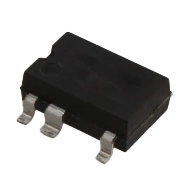
LNK304DN-TL Power Integrations
-
LNK304GN-TL Power Integrations
-
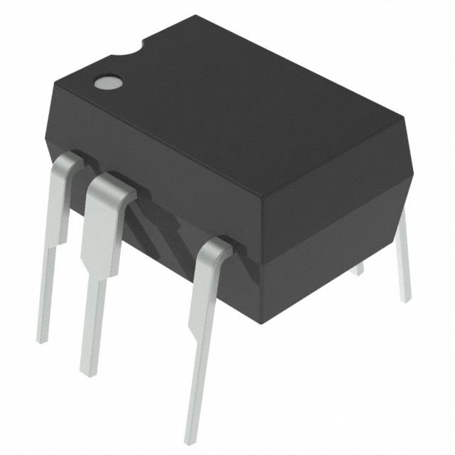
LNK304DG-TL Power Integrations
-
TNY277PN Power Integrations
-
TNY276PN Power Integrations
-
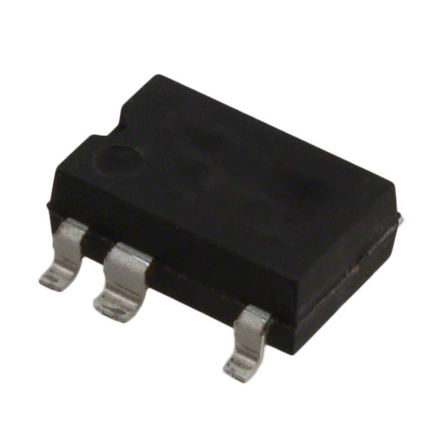
TNY278PN Power Integrations
-
TNY278GN-TL Power Integrations
-
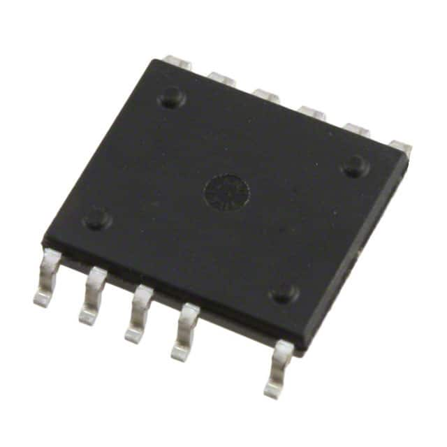
TNY280GN-TL Power Integrations
-
TOP266KG-TL Power Integrations
-
TOP258PN Power Integrations
-
TOP253PN Power Integrations
-
TOP253PNAU Power Integrations

- 1500+ Daily average RFQ Volume

- 20,000.000 Standard Product Unit

- 1800+ Worldwide Manufacturers

- 15,000+ In-stock Warehouse