5 Ways Using an Op-Amp as a Comparator Will Burn You (And What to Use Instead)
5 Ways Using an Op-Amp as a Comparator Will Burn You (And What to Use Instead)
Every engineer has done it. You've got a quad op-amp on the board, three channels doing signal conditioning, and one sitting idle. The BOM is locked. The PCB is laid out. And you just need a simple threshold detector - a comparator, basically.
So you wire the spare op-amp channel open-loop, add a reference voltage to one input, and call it a day.
It works on the bench. It passes the first round of testing. And then - sometimes weeks later - it doesn't.
Here are the five ways that shortcut burns you, ranked from "annoying" to "board respin."
Mistake #1: The Input Clamp Diodes You Didn't Know Were There
This is the big one. Most op-amps have back-to-back protection diodes between the IN+ and IN− pins. In normal closed-loop operation, the inputs sit at nearly the same voltage, so these diodes never conduct. You'd never know they exist.
But wire that op-amp as a comparator, apply a 3V differential, and suddenly you're dumping current through diodes rated for microamps of protection - not milliamps of steady-state conduction.
What happens? One input starts tugging on the other through the diode path. Your reference voltage shifts. Your signal gets distorted. And if the current is high enough, those protection diodes fail - permanently. The op-amp still "works" as an amplifier, but its offset voltage drifts permanently. Cumulative damage.
The fix: Use a comparator. The LM393, LMV393, and LM339 families don't have input clamp diodes - they're built for large differentials. If you must use an op-amp, pick the LM358 or LM324 (no input diodes). But they're still slower than real comparators. Which brings us to Mistake #2.
Mistake #2: Saturation Recovery Is 100× Slower Than You Think
An op-amp's internal compensation capacitor - the same one that keeps it stable with negative feedback - turns into a boat anchor when the output saturates. Coming out of saturation means charging or discharging that capacitor from a rail voltage, and it takes microseconds.
A comparator has no compensation capacitor. It switches in nanoseconds, cleanly, every time.
In a 100kHz SMPS, one cycle is 10µs. If your fault detector takes 15µs to respond, the MOSFET is dead before the op-amp wakes up. A comparator responds in 200ns - 2% of a cycle. That's the gap between a protected power stage and a warranty return.
Mistake #3: The Output Voltage Is Wrong for Your Logic
Comparators use open-collector outputs. One pull-up resistor to whatever logic voltage you need - 1.8V, 3.3V, 5V - done. Op-amps have push-pull outputs swinging to near the rails. If your op-amp runs from ±12V and your MCU GPIO is 3.3V, connecting them directly fries the GPIO.
So you add a level shifter. And a clamp diode. And now your "free" spare op-amp has cost you three extra components and the PCB area they occupy. The dedicated comparator with a pull-up to 3.3V would have been one resistor.
Mistake #4: Phase Reversal - When HIGH Means LOW
Many bipolar and JFET-input op-amps invert their output phase when the input common-mode range is exceeded. You set up a window comparator for overvoltage protection. The voltage rises. The op-amp's input goes beyond VCC−1.5V. The output flips to the opposite state.
Your protection circuit just became a pass-through.
This isn't a hypothetical edge case. It's documented in TI's application notes (sloa277) for the LM358, LM324, and dozens of other popular op-amps. Comparators are designed to avoid phase reversal. Op-amps aren't - because in normal closed-loop use, the inputs never leave the common-mode range.
Mistake #5: The "It Works on the Bench" Trap
This is the mistake that makes the other four dangerous. You breadboard it. It switches fine at room temperature with a clean bench supply. You ship it.
Then the product hits the field. Temperature swings from −20°C to 70°C. The supply rail has 200mV of ripple. The input signal has noise. Now:
- Leakage current through the input diodes is 10× higher at 70°C.
- Saturation recovery takes even longer at cold temperatures.
- Without hysteresis, noise causes bursts of 10MHz oscillation at every transition.
- Your 3.3V MCU GPIO, which drove the op-amp input fine at 25°C, can't quite reach the input threshold at −20°C.
A comparator data sheet characterises all of these conditions. An op-amp data sheet doesn't - because the manufacturer never intended you to use it this way.
So When Is It Actually OK?
There's exactly one defensible scenario: spare LM358 or LM324 channel (no input diodes), comparison speed in milliseconds, differential input under a few hundred mV, benign temperature range, and a BOM line or PCB respin you genuinely cannot afford for a separate comparator IC.
In that case: add hysteresis. Test across temperature. And know that you're making a calculated trade-off, not a free lunch.
For everything else, reach for a comparator.
What Should You Use Instead?
| Scenario | Comparator | Why |
|---|---|---|
| 3.3V/5V battery-powered threshold detection | LMV393IDR | 50µA quiescent, 200–600ns, 2.7–5.5V |
| 12V/24V industrial and automotive | LM393DR | 2–36V supply, 300ns–1.5µs, industry standard pinout |
| New design, inputs may go negative | LM393LVDR | 1.65–5.5V, 35µA, phase-reversal protection built in |
| High-speed fault detection (<50ns) | TLV3501 | 4.5ns propagation delay, push-pull output |
| Quad channel, multi-rail monitoring | LM339DR | 4 comparators in SOIC-14, 2–36V |
The bottom line. Using an op-amp as a comparator is like using a screwdriver as a chisel. It works until it doesn't - and when it doesn't, the damage is done. A comparator costs about the same, fits the same footprint, won't surprise you. Start with the right part.
Related: Comparator vs Op-Amp - Full Comparison & Selection Guide | LMV393IDR Product Page | LM393DR Product Page
Related information
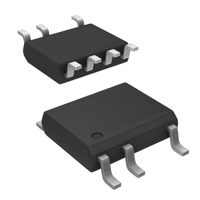
-
LNK304DN-TL Power Integrations
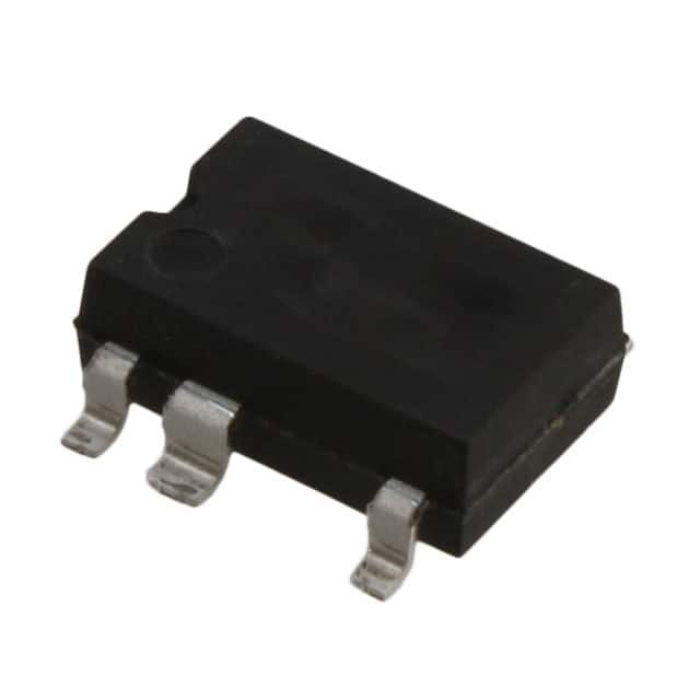
-
LNK304GN-TL Power Integrations
-
LNK304DG-TL Power Integrations
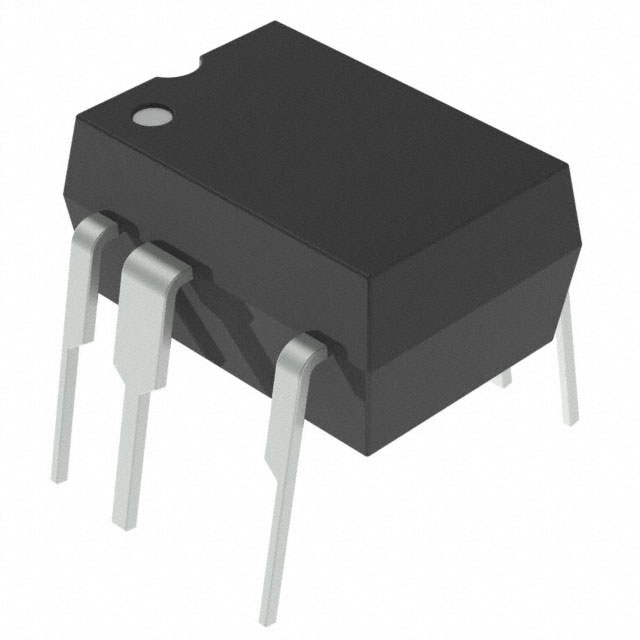
-
TNY277PN Power Integrations
-
TNY276PN Power Integrations
-
TNY278PN Power Integrations
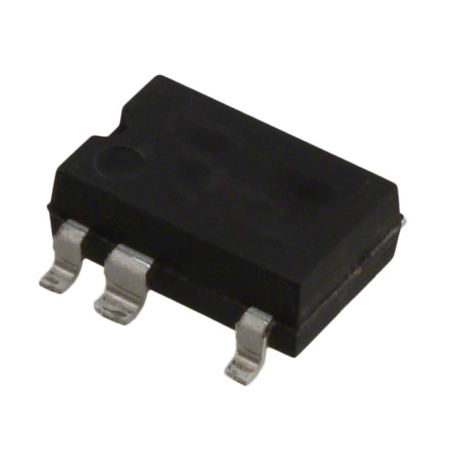
-
TNY278GN-TL Power Integrations
-
TNY280GN-TL Power Integrations
-
TOP266KG-TL Power Integrations
-
TOP258PN Power Integrations
-
TOP253PN Power Integrations
-
TOP253PNAU Power Integrations

- 1500+ Daily average RFQ Volume

- 20,000.000 Standard Product Unit

- 1800+ Worldwide Manufacturers

- 15,000+ In-stock Warehouse