Comparator vs Op-Amp — Full Comparison & Selection Guide
Comparator vs Op-Amp - Full Comparison & Selection Guide | ICMASS
A comparator tells you which of two voltages is bigger and gives a clean logic-level answer. An op-amp amplifies the difference between two voltages and gives you a linear output proportional to that difference. Same triangle symbol in the schematic. Completely different job.
Need a digital high/low decision - undervoltage lockout, zero-crossing, window comparator? Use a comparator. Need amplification, filtering, buffering? Use an op-amp. Using an op-amp as a comparator is the most common analog shortcut that comes back to bite you in production.
Comparator vs Op-Amp: Side-by-Side Comparison
| Parameter | Comparator | Op-Amp |
|---|---|---|
| Primary function | Compare two voltages, output logic HIGH/LOW | Amplify voltage difference, output linear proportional signal |
| Operation mode | Open-loop (no negative feedback). Hysteresis via positive feedback | Closed-loop (negative feedback sets gain) |
| Output type | Open-collector/drain or push-pull; saturates to rail | Push-pull, linear; swings between rails but stays in active region |
| Output states | Binary: HIGH or LOW | Analog: any voltage between the rails |
| Switching speed | 200ns–1µs (propagation delay) | 1–20µs (recovery from saturation) |
| Internal compensation | No Miller capacitor - maximized for speed | Miller compensation capacitor - ensures closed-loop stability |
| Differential input range | Wide: can withstand large VIN+ − VIN− | Often limited: back-to-back protection diodes clamp at ~±0.7V |
| Input protection diodes | Generally none between inputs | Common on bipolar and many CMOS op-amps (check datasheet) |
| Phase reversal risk | Low; designed to avoid it | Present on many non-RRIO op-amps when inputs exceed CM range |
| Hysteresis | Built-in on some; easy to add with positive feedback | Requires positive feedback (making it a comparator in practice) |
| Logic-level compatible | Yes - open-collector pulls to any logic rail | No - output swings to analog rails; needs level translation |
| Supply current (typ) | 50µA–500µA (low-power comparators) | 50µA–2mA (varies widely; general-purpose ~0.5–1mA/ch) |
| Key datasheet specs | Propagation delay, overdrive, hysteresis, output sink current | GBW, slew rate, phase margin, VOS, CMRR, PSRR |
| Typical gain | 200V/mV (open-loop, but irrelevant - it's always saturated) | 100–130dB open-loop (used closed-loop at set gain) |
| Price (relative) | Comparable; dedicated comparators often slightly cheaper | Comparable; general-purpose op-amps among cheapest ICs |
| Pinout (dual SOIC-8) | Same industry-standard pinout as dual op-amp | Same industry-standard pinout as dual comparator |
The pinout is identical. So why different parts? The silicon is optimized for opposite goals. An op-amp's compensation capacitor gives stability with feedback - but slow saturation recovery. A comparator skips it: blazing fast switching, but oscillates if you close a feedback loop around it.
Key Differences (Why You Can't Just Swap Them)
1. Output Stage: Open-Collector vs Push-Pull Linear
Comparators use open-collector (or open-drain) outputs. The output pin can only pull LOW - it needs an external pull-up resistor to go HIGH. This lets you pull up to any voltage: 3.3V logic, 5V logic, 12V, even 24V for driving MOSFET gates directly. One comparator, any logic level.
Op-amps use push-pull outputs designed for linear operation. They source and sink current, but aren't optimized for slamming rail-to-rail at speed. When the output saturates, internal transistors take microseconds to recover - by which time your overcurrent protection should have already tripped.
2. Speed: Propagation Delay vs Saturation Recovery
A comparator is designed to switch and recover in nanoseconds. An op-amp, when driven into saturation, takes 2–15µs to recover - 10–100× slower. For a 100kHz SMPS fault-detection circuit, 2µs is the difference between a protected MOSFET and a dead one.
3. Input Stage: Differential Voltage Tolerance
4. When You Actually Can Use an Op-Amp as a Comparator
There's one legitimate scenario: you have a spare op-amp channel in a quad package, your comparison speed is measured in milliseconds, the differential input voltage stays under ±0.3V, and adding a separate comparator IC would mean a BOM line and PCB spin.
In that case, use an LM358 or LM324 - they lack input clamp diodes. Add hysteresis. Test across temperature. And never do this with a precision op-amp like the OPA227 or NE5532 - the input diodes will destroy signal integrity and possibly the part.
When to Choose a Comparator
- Any speed-sensitive threshold detection. Undervoltage lockout, overcurrent protection, zero-crossing detection. Every microsecond of delay is more stress on your power stage.
- Digital logic interface needed. The open-collector output pulls directly to your logic rail - 1.8V, 3.3V, 5V - with one pull-up resistor. No level translation circuit needed.
- Window comparator. Two comparators, one package, wired-OR outputs. Tells you whether a signal is inside or outside a voltage window with a single logic signal.
- Large input differential expected. Any circuit where the two inputs might be volts apart in normal operation.
- Relaxation oscillator or PWM generator. Comparators switch cleanly with hysteresis - the LM393/LMV393 is the standard building block for this.
When to Choose an Op-Amp
- Amplification, filtering, buffering, integration. Anywhere you need a linear relationship between input and output.
- Closed-loop control. Error amplifiers in power supplies, PID controllers, current-sense amplifiers - all need the linear gain and phase margin that only an op-amp provides.
- Sensor signal conditioning. Thermocouple amplifiers, photodiode transimpedance amps, strain gauge bridges - you're amplifying microvolts, not comparing them.
- Audio and precision AC. Active filters, summing amplifiers, balanced line drivers - all rely on the op-amp's linearity, not its saturation behavior.
- Impedance buffering. Voltage followers between high-Z sources and low-Z loads need the op-amp's feedback-stabilized unity gain.
Recommended Parts
| Category | Model | Key Spec | Best For |
|---|---|---|---|
| Low-Voltage Comparator | LMV393IDR | 2.7–5.5V, 50µA, 200–600ns | Battery-powered threshold detection, 3.3V MCU window comparator |
| Standard Comparator | LM393DR | 2–36V, 400µA, 300ns–1.5µs | 12V/24V industrial, automotive, line-powered |
| General-Purpose Op-Amp | LM358DR | 3–32V, 0.8mA, 1MHz GBW, 0.5V/µs | DC/low-frequency signal conditioning, unity-gain buffer |
| Low-Voltage RRIO Op-Amp | LMV358IDR | 2.7–5.5V, 210µA, 1MHz GBW, RRIO | 3.3V/5V single-supply near-rail signals |
| Low-Voltage Comparator w/ Protection | LM393LVDR | 1.65–5.5V, 35µA, 600ns, phase-reversal protection | New designs where inputs may go negative |
Frequently Asked Questions
Q1: Can I use an op-amp as a comparator?
A: Generally no - not unless you're in a specific, slow, low-differential-voltage situation and you've tested thoroughly. Most op-amps have input clamp diodes (conduction at ±0.7V), slow saturation recovery, and logic-incompatible outputs. The LM358/LM324 lack input diodes but are still slower than real comparators. For production, use a dedicated comparator.
Q2: Why do comparators and op-amps use the same schematic symbol?
A: Historical convention - they share the same differential-input, high-gain architecture. But the internal silicon is optimized differently. Think of it like a pickup truck and a race car: both have an engine and four wheels, but you wouldn't use one for the other's job.
Q3: What happens if I use an op-amp as a comparator at high speed?
A: Slow output, possible wrong state, potential cumulative damage. The compensation capacitor delays saturation recovery. Input diodes may conduct. Some op-amps draw excessive current when railed. In fault detection, the op-amp is 10–100× slower than a comparator - by the time it trips, the FET is already dead.
Q4: LM358 or LM393 - which one for battery-low detection?
A: LM393 (comparator). Faster switching, and the open-collector output drives an MCU GPIO or LED directly. The LM358 works in a pinch since it lacks input clamp diodes, but saturation recovery is slower. For a battery-low indicator with a spare LM358 already on the board, it's acceptable. For production, use the LM393.
Q5: Why do comparators have open-collector outputs?
A: Flexibility. One pull-up resistor sets any logic level - 1.8V, 3.3V, 5V, 12V. Multiple open-collector outputs wire-OR naturally: any comparator pulling low pulls the shared node low. For a window comparator, tie both outputs to one pull-up - single Power-Good signal, no extra logic.
Q6: Do I need hysteresis on a comparator?
A: Almost always - if your signal changes slowly or has noise. Without hysteresis, a comparator with a slow input oscillates at the transition, producing a burst of HF pulses instead of a clean edge. Add positive feedback: a resistor from output to non-inverting input. Set the hysteresis window 2–3× larger than your peak-to-peak noise.
Q7: What's the difference between LMV393 and LM393 - which comparator should I stock?
A: LMV393 for low-voltage (2.7–5.5V, 50µA). LM393 for standard (2–36V). If your designs span both 3.3V and 12V rails, stock both. The LM393DR covers the widest range. The LMV393IDR is right when battery life or 3.3V-only operation matters.
Q8: Can a comparator be used as an op-amp?
A: No. A comparator oscillates if you close a negative feedback loop around it. Comparators are intentionally uncompensated for maximum speed. Without the Miller capacitor that stabilizes op-amps, a comparator in closed-loop mode becomes an oscillator - not an amplifier. The two parts are not interchangeable in either direction.
Related Products
Related information
-
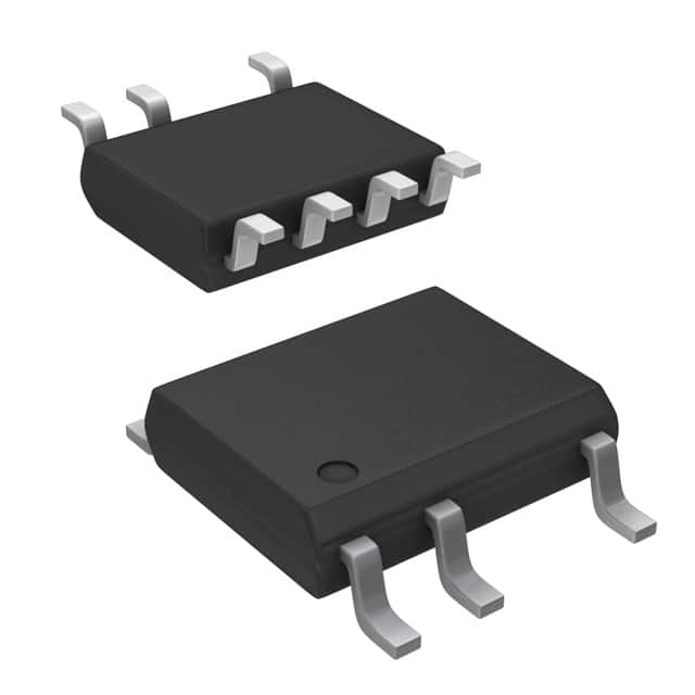
LNK304DN-TL Power Integrations
-
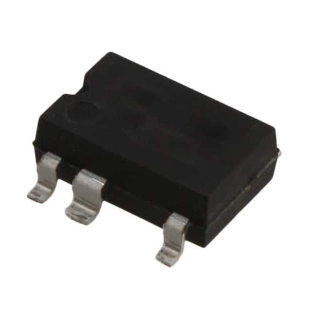
LNK304GN-TL Power Integrations
-
LNK304DG-TL Power Integrations
-
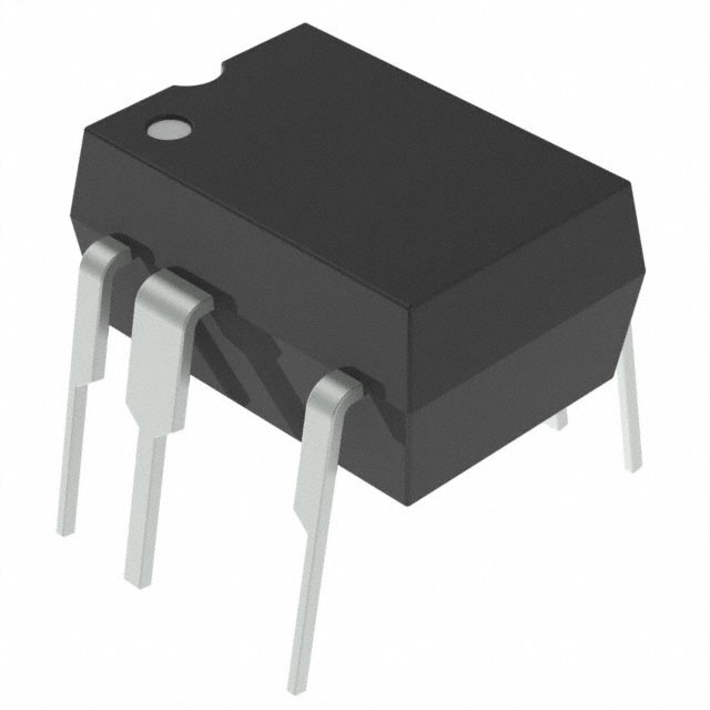
TNY277PN Power Integrations
-
TNY276PN Power Integrations
-
TNY278PN Power Integrations
-
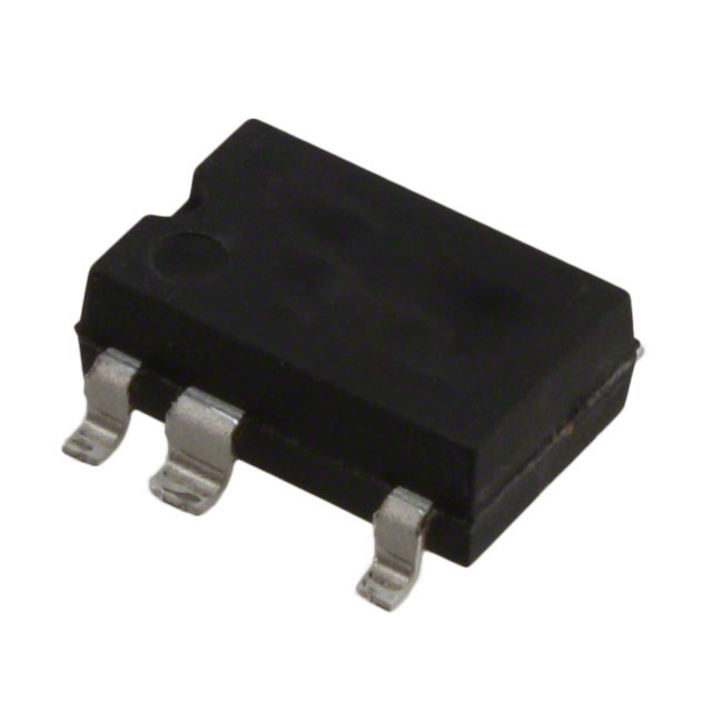
TNY278GN-TL Power Integrations
-
TNY280GN-TL Power Integrations
-
TOP266KG-TL Power Integrations
-
TOP258PN Power Integrations
-
TOP253PN Power Integrations
-
TOP253PNAU Power Integrations

- 1500+ Daily average RFQ Volume

- 20,000.000 Standard Product Unit

- 1800+ Worldwide Manufacturers

- 15,000+ In-stock Warehouse