PC817 Pinout, Specifications & Common Mistakes
PC817 Pinout, Specifications & Common Mistakes | ICMASS
The PC817 is a 4-pin DIP phototransistor optocoupler from Sharp: an IR LED facing an NPN phototransistor across a 5,000Vrms isolation barrier. Pass a digital signal between a 3.3V MCU and a 24V PLC input. Drive a MOSFET gate without sharing a ground. This is the part you reach for.
But the PC817 also generates more "why isn't this working?" forum posts than any other optocoupler. The LED needs a current-limiting resistor. The output needs a pull-up. CTR varies 12:1 across grades. Switching speed tops out at 80kHz. And in always-on designs, CTR degradation will catch you.
PC817 Pinout and Pin Functions
| Pin | Name | Function | Notes |
|---|---|---|---|
| 1 | Anode | IR LED positive terminal | Connect to signal source via current-limiting resistor |
| 2 | Cathode | IR LED negative terminal | Connect to input-side ground |
| 3 | Emitter | Phototransistor emitter | Connect to output-side ground |
| 4 | Collector | Phototransistor collector | Connect to VCC via pull-up resistor; output signal taken here |
Logic convention. The output is inverted: LED ON → phototransistor conducts → collector pulled LOW. LED OFF → phototransistor off → collector pulled HIGH by RL. If your firmware expects non-inverted logic, flip it in software or add a second inverting stage on the output.
Key Specifications
| Parameter | Value | Condition |
|---|---|---|
| Isolation Voltage | 5,000 Vrms | Input to output, 1 min |
| LED Forward Voltage (VF) | 1.2V typ / 1.4V max | IF = 20mA |
| LED Forward Current (IF max) | 50mA | Continuous; typical design target: 5–20mA |
| LED Reverse Voltage (VR max) | 6V | |
| Collector-Emitter Voltage (VCEO) | 80V | IC = 0.1mA |
| Collector Current (IC max) | 50mA | |
| Current Transfer Ratio (CTR) | 50–600% | IF = 5mA, VCE = 5V; varies by grade |
| CTR by Grade | A: 80–160% / B: 130–260% / C: 200–400% / D: 300–600% | |
| Rise Time (tr) | 4µs typ / 18µs max | VCE=2V, IC=2mA, RL=100Ω |
| Fall Time (tf) | 3µs typ / 18µs max | Same conditions |
| Cut-off Frequency (fc) | 80kHz | VCE=5V, IC=2mA, RL=100Ω |
| Total Power Dissipation | 200mW | |
| Operating Temperature | -30 to +100°C |
CTR by grade — a 12:1 spread from worst-case A to best-case D. Buy ungraded PC817 and your CTR could be anywhere from 50% to 600%. Design for the minimum. Design for typical and your production line will see failures.
Bar width = CTR range span relative to Grade D. Design rule: IF × CTRmin ≥ 2 × IC(load). This guarantees saturation even at worst-case CTR.
Typical Application Circuits
MCU GPIO → PC817 → MOSFET gate drive. This is the most common isolation pattern. The MCU drives the LED through a 330Ω resistor (5V GPIO) or 220Ω (3.3V). The output pulls the MOSFET gate high through a 10kΩ pull-up. The 100kΩ gate-to-source resistor prevents parasitic turn-on from phototransistor leakage.
Common Mistakes When Using PC817
1. Missing LED current-limiting resistor. The #1 failure mode. Connecting a voltage source directly to pin 1 burns the IR LED instantly. Calculate RLED = (Vsupply − 1.2V) / IF where IF = 5–20mA. For 5V: ~330Ω. For 3.3V: ~220Ω. For 24V: ~4.7kΩ.
2. Missing pull-up resistor on the output. The phototransistor can only pull current down, not up. Without a pull-up resistor from pin 4 to VCC, the collector floats and the output voltage is undefined. Leakage current through the phototransistor can partially turn on downstream MOSFETs. Use 1–10kΩ for general switching.
3. No gate-to-source pulldown when driving a MOSFET. Phototransistor leakage (up to 100nA dark current) slowly charges the MOSFET gate capacitance even with the LED off. A 100kΩ gate-to-source resistor bleeds this off. Without it, the MOSFET turns on hours later for no apparent reason.
4. Designing for typical CTR instead of minimum. Ungraded PC817 CTR ranges from 50% to 600%. If your design needs 2mA collector current at 300% CTR, you get 0.33mA at worst-case 50%. Not enough to saturate. Always design for the minimum CTR of your grade.
5. Ignoring CTR degradation in always-on designs. CTR drops to ~50% of initial value over the operating life. At elevated temperature (60°C+), it degrades faster. For a product that runs 24/7, design for CTREOL = CTRmin × 0.5 (aging) × 0.75 (85°C operation). Or switch to PC817C/D grade for more margin.
6. Expecting high-speed switching from a general-purpose optocoupler. The PC817's cut-off frequency is 80kHz under optimal conditions (RL=100Ω). With a more typical 10kΩ pull-up, the RC time constant with junction capacitance limits usable bandwidth to ~25kHz. If you need 100kHz+ isolated digital signals, use a high-speed logic-output optocoupler.
7. Floating inputs with long wires. In automotive or industrial settings with long cable runs, the LED input acts as an antenna. Noise false-triggers the optocoupler. Add a pulldown resistor (10–100kΩ to GND) on the input side. A 1–10nF cap across the LED shunts high-frequency noise.
Frequently Asked Questions
Q1: What resistor value do I need for the LED side?
A: R = (Vsupply − 1.2) / IF. For 5V at 10mA: ~390Ω. For 3.3V at 5mA: ~420Ω. For 12V at 5mA: ~2.2kΩ. For 24V at 5mA: ~4.7kΩ. Target 5–10mA for reliable switching; 20mA only if you need the lowest possible VCE(sat).
Q2: Which CTR grade should I choose?
A: PC817C (200–400%) is the safe default for most designs. Grade A is fine for 5V digital logic if your LED current is above 10mA. Grade D is overkill unless you're running the LED at very low current or need margin for long-term CTR degradation. If you're buying ungraded PC817, design for the 50% minimum CTR.
Q3: Why is my PC817 output always low?
A: Likely no pull-up resistor on pin 4, or the pull-up is too large. Check that pin 4 has a resistor to VCC (1–10kΩ). Also verify the LED is actually off: measure voltage across pins 1–2; if it's above ~1V, your MCU or driving circuit is sourcing current when you think it isn't.
Q4: Can PC817 be used for analog signal isolation?
A: Not well, and not linearly. The PC817 is a digital switching optocoupler. CTR varies with IF, temperature, and aging. For analog isolation, use a linear optocoupler like the IL300 or HCNR200, which have matched photodiodes for servo-linearisation.
Q5: What's the difference between PC817 and 4N35?
A: Both are 4-pin DIP phototransistor optocouplers, but the PC817 has higher isolation (5kV vs 3.5kV) and more CTR grade options. The 4N35 is a 6-pin DIP with a base pin brought out (pin 6), which allows external base-emitter resistor connection for speed-up. The PC817 is simpler: 4 pins, no base access. For most digital isolation applications, they're interchangeable as long as you respect the pinout differences.
Related information
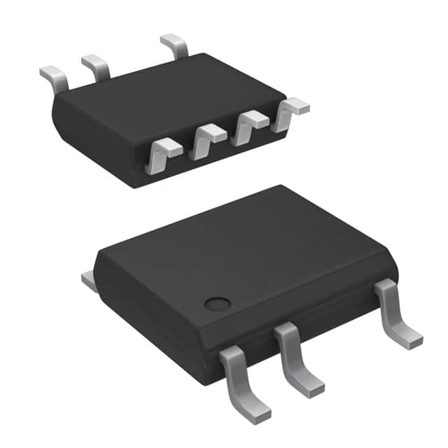
-
LNK304DN-TL Power Integrations
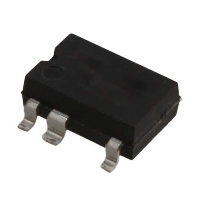
-
LNK304GN-TL Power Integrations
-
LNK304DG-TL Power Integrations
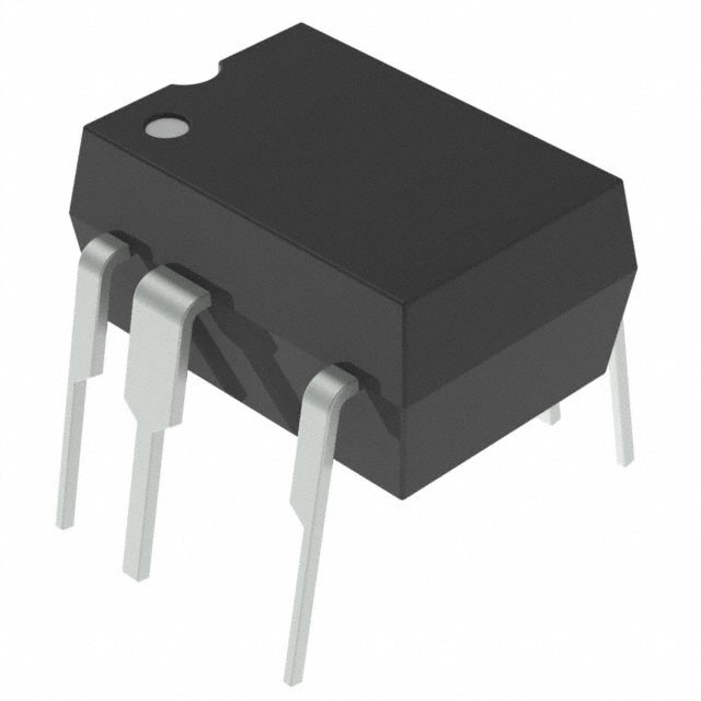
-
TNY277PN Power Integrations
-
TNY276PN Power Integrations
-
TNY278PN Power Integrations
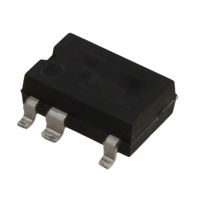
-
TNY278GN-TL Power Integrations
-
TNY280GN-TL Power Integrations
-
TOP266KG-TL Power Integrations
-
TOP258PN Power Integrations
-
TOP253PN Power Integrations
-
TOP253PNAU Power Integrations

- 1500+ Daily average RFQ Volume

- 20,000.000 Standard Product Unit

- 1800+ Worldwide Manufacturers

- 15,000+ In-stock Warehouse