


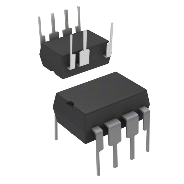
Power Integrations LNK305PN-TL

- Part No.:
- LNK305PN-TL
- Manufacturer:
- Power Integrations
- Category:
- AC DC Converters, Offline Switches
- Package:
- 8-DIP (0.300", 7.62mm), 7 Leads
- Description:
- IC OFFLINE SWITCH MULT TOP 8DIP
- Quantity:
-
Unit Price:$0
Ext Price:$0
- Payment:
-

- Shipping:
-


LNK305PN-TL Information
- Specifications
- Product Details
- Comparison
- Tags
- Product attributes
- Attribute value
- Manufacturer:
- Power Integrations
- Series:
- LinkSwitch®-TN
- Package/Case:
- 8-DIP (0.300", 7.62mm), 7 Leads
- Packaging:
- Product Status:
- Active
- Output Isolation:
- Non-Isolated
- Internal Switch(s):
- Yes
- Voltage - Breakdown:
- 700V
- Topology:
- Buck, Buck-Boost, Flyback
- Voltage - Start Up:
- -
- Voltage - Supply (Vcc/Vdd):
- -
- Duty Cycle:
- 69%
- Frequency - Switching:
- 66kHz
- Power (Watts):
- -
- Fault Protection:
- Current Limiting, Open Loop, Over Temperature, Short Circuit
- Control Features:
- -
- Operating Temperature:
- -40°C ~ 150°C (TJ)
- Grade:
- -
- Qualification:
- -
- Supplier Device Package:
- 8-PDIP-B
- Mounting Type:
- Through Hole
LNK305PN-TL - 700V Offline Switcher IC by Power Integrations
The LNK305PN-TL is an integrated offline switcher IC from Power Integrations' LinkSwitch-TN family. It packs a 700V power MOSFET, oscillator, and On/Off control into a single 8-pin PDIP package, delivering up to 120 mA in a buck topology - no transformer needed, no bias supply required.
It's designed to replace linear and capacitor-dropper (cap dropper) power supplies. The IC handles universal AC input (85 VAC to 265 VAC) and runs at 66 kHz with built-in frequency jittering that cuts EMI by about 10 dB. Start-up and operating power come directly from the DRAIN pin, so you don't need a separate bias winding or auxiliary supply.
The "-TL" suffix means tape-and-reel packaging, suitable for automated assembly. The non-TL variant (LNK305PN) is the standard tube version. They're the same silicon. For a non-isolated buck design at 120 mA, this IC is one of the simplest parts on the market - just a bridge rectifier, an inductor, a few capacitors, and you have a 12V or 5V rail from mains.
What Is LNK305PN-TL and How Does It Work?
It's a monolithic switcher with a 700V MOSFET on-chip. The control method is On/Off regulation: the IC switches at 66 kHz when the output is below the regulation threshold, and skips cycles when the output is above it. This keeps the output regulated without complex compensation, and the built-in frequency jitter spreads the switching energy across a wider spectrum to reduce EMI.
The BP (bypass) pin is the key to how it starts: a small capacitor on BP stores enough energy to run the IC during startup. Once the output is established, the IC feeds itself from the DRAIN pin through an internal high-voltage current source. That means no external bias supply, no transformer winding, no start-up resistors - a genuine drop-in replacement for resistive dropper circuits.
The LinkSwitch-TN family scales by current: the LNK302 is the entry point (80 mA), the LNK304 delivers 170 mA in buck-boost, and the LNK305 tops out at 280 mA in buck-boost. The LNK305PN fits in the middle - 120 mA in buck, 175 mA in buck-boost, enough for most low-power auxiliary supplies.
Position in the product line: The LinkSwitch-TN family (LNK302 through LNK306) covers 80 mA to 360 mA. The LNK305 is the third rung, a step up from the LNK304 (which we also stock). Above the LNK306, Power Integrations has the LinkSwitch-LP and LinkSwitch-XT families for higher-power offline designs. For 12V at 100 mA - think microcontrollers, relays, LED indicators - the LNK305 is the natural sweet spot.
What Are the Specifications of LNK305PN-TL?
| Parameter | Value | Notes |
|---|---|---|
| Manufacturer | Power Integrations | LinkSwitch-TN family |
| MOSFET Breakdown Voltage | 700 V | Integrated avalanche-rated |
| Output Current (Buck) | 120 mA | 120/220 VAC universal |
| Output Current (Buck-Boost) | 175 mA | Standard configuration |
| Switching Frequency | 66 kHz typical | With 6 kHz jitter for EMI |
| Input Voltage | 85 VAC – 265 VAC | Universal, 47–440 Hz |
| No-Load Power | ~50 mW @ 115 VAC | ~80 mW @ 230 VAC |
| RDS(on) | 12 Ω typ | At 25°C junction |
| Thermal Shutdown | +135°C min | Hysteretic auto-recovery |
| Protection | OCP, OTP, Auto-restart | Short-circuit + open-loop |
| Topologies | Buck, Buck-Boost, Flyback | Non-isolated or isolated |
| Package | PDIP-8B (7-pin populated) | DIP-8, one pin removed |
| Operating Temp | -40°C to +150°C | Junction |
| EMI Standard | EN55022 Class B | With frequency jitter + pi-filter |
Key Numbers That Matter
- 700V MOSFET: This gives you headroom above the peak of a 265 VAC rectified line (375V). The 700V rating handles typical mains transients without an external clamp. But for areas with poor grid stability, we still recommend a varistor on the input. The MOSFET is avalanche-rated, so it survives mild overvoltage events - but repeated events wear it down.
- 12 Ω RDS(on): That's high compared to modern switching regulators, but keep in mind this is a 700V MOSFET designed for low cost and simplicity, not efficiency. At 120 mA, conduction loss is about 170 mW - manageable. The thermal shutdown at 135°C gives you room, but the PDIP package has a limited ability to shed heat. We've seen designs running at 100 mA in a sealed enclosure hit 80°C case temperature, which is fine, but margins are tight.
- Frequency jitter (6 kHz spread): This reduces peak EMI by about 10 dB, which is the difference between passing EN55022 Class B and failing it. It's enabled by default - you don't need to configure it. But the jitter alone isn't enough; you still need a pi-filter on the input and a well-laid-out board.
- 120 mA in buck, 175 mA in buck-boost: The buck-boost rating is higher because the duty cycle and stress on the MOSFET are different. If you need a negative rail or an isolated output, you'll get more current from the same part - but with more components and a larger inductor.
What Is LNK305PN-TL Used For?
Appliance Control Power Supplies
This is the biggest application. Washing machines, microwave ovens, air conditioners - any white goods that need a low-current DC rail (5V or 12V) for a microcontroller and relay drivers. The LNK305 replaces a cap-dropper circuit with a switcher that's smaller, cooler, and compliant with Energy Star no-load requirements (< 100 mW). From our experience, appliance manufacturers are the largest buyers of this IC. They value the simplicity: 12 components for a complete supply, no transformer, no feedback loop design.
LED Drivers for Indicators and Small Loads
A constant-voltage LED driver for 12V indicator strips at up to 120 mA. The LNK305's current limit is built-in, so the LED string is protected from short circuits. For dimmable or constant-current designs, you'd look at the LinkSwitch-PL family instead. But for a simple On/Off indicator light, the LNK305 is cost-effective and reliable.
Replacement for Resistive Dropper (Cap Dropper) Supplies
The classic cap dropper circuit (a resistor + capacitor + zener) is cheap but has problems: it's not short-circuit protected, it dissipates heat as a function of input voltage (worse at 240V than 120V), and it has poor line regulation. Swapping in an LNK305 gives you a regulated output, fold-back current limiting, and Energy Star-compliant no-load power. The BOM cost is about $0.40 higher, but you save on heat sinking and compliance testing. We've helped several customers make this exact transition.
Industrial Auxiliary Supplies
24V industrial buses, PLCs, and sensors often need a small auxiliary rail for the control circuitry. The LNK305's 700V rating handles the 380V peaks from a 240VAC rectified line, and the wide input range covers the voltage drops you see on long industrial wiring runs.
Common Design Issues - and How to Avoid Them
The LNK305 is simple to design with, but there are traps. Here are the ones that come up most on Power Integrations' own forum:
Pulse Bunching at Moderate Loads
Under 50–150 mA load, the IC can enter burst mode even when it shouldn't. The symptom: the inductor current ramps up cycle by cycle, the RDS(on) of 12 Ω causes the MOSFET to heat up, and eventually the part hits thermal shutdown. The fix is usually feedback-related - lower the feedback gain by using an optocoupler with a lower CTR, or add series resistance in the feedback path. If you're running a non-isolated direct-feedback design, check the BP pin capacitor value: changing it alters the burst behavior significantly.
Output Ripple Worse Than Expected
Several engineers report ripple of 500 mV to 1 V when the datasheet suggests ~150 mV. The cause is almost always one of three things: (1) the output capacitor's ESR is too high - use a low-ESR type (< 0.2 Ω at 100 kHz, like Hitano EXR series); (2) the diode is too slow - standard 1N4007 is not suitable, use an ultra-fast recovery diode with tRR ≤ 75 ns like the UF4005 or UF4007; or (3) the feedback capacitor (Cfb) is too large - reducing it from 10 μF to 1 μF can cut ripple in half.
Audible Noise (Buzzing)
If the inductor saturates, you'll hear it. The LNK305 needs an inductor with a saturation current rating of at least 500 mA - not just the RMS current rating, which misleads. A 470 μH inductor with 500 mA saturation typically solves the audible noise issue. The 1 mH inductor in some reference designs actually makes it worse because it saturates earlier at high line voltage. We stock shielded inductors from Würth that work well with this IC.
Regulation Loss Above 220 VAC
Some designs work fine at 120 VAC but lose regulation at 220–265 VAC. The culprit is parasitic coupling between the ground plane under the feedback resistors and the switching noise on the output. Fix: remove the ground plane under the feedback traces and use guard rings around the feedback network. The Power Integrations community forum has a detailed thread on this exact issue.
Layout Guidelines
These rules from the datasheet and application notes (AN-37, DER-49) make the difference between a design that passes EMI testing and one that doesn't:
- Minimize the switching current loop. The highest di/dt loop runs from the IC's DRAIN pin through the inductor, the output capacitor, the catch diode, and back to the SOURCE pin. Keep this loop physically small on the PCB.
- Pi-filter on the input. A C-L-C pi-filter before the bridge rectifier reduces conducted EMI by 20–30 dB. The frequency jitter handles the rest.
- No ground plane under feedback traces. The feedback path is high-impedance. Any capacitive coupling from the switching node injects noise into the feedback. Route the feedback on the top layer with a ground guard ring on the layer below.
- Keep the BP pin capacitor close. The bypass capacitor on the BP pin provides the internal supply for the control logic. A 1 μF ceramic within 5 mm of the pin is the target.
- Use a fast diode. As mentioned above, the catch diode must have tRR ≤ 75 ns. We stock UF4005 and UF4007 for exactly this purpose.
LNK305PN-TL vs. the Competition
| Part | Current (Buck) | MOSFET | Frequency | Topology | 1k Price |
|---|---|---|---|---|---|
| LNK305PN-TL | 120 mA | 700V integrated | 66 kHz | Buck / Buck-Boost | $0.63 |
| LNK304PN-TL | 170 mA* | 700V integrated | 66 kHz | Buck / Buck-Boost | $0.58 |
| LNK306PN-TL | 360 mA* | 700V integrated | 66 kHz | Buck / Buck-Boost | $0.75 |
| VIPer12A | ~60 mA (flyback) | 730V integrated | 60 kHz | Flyback / Buck | $0.70 |
*Buck-boost configuration; buck ratings differ. LNK304: 120 mA buck, LNK305: 175 mA buck-boost, LNK306: 225 mA buck.
Frequently Asked Questions
Q1: Is the LNK305PN-TL the same as LNK305PN?
A: Electrically, yes. The "-TL" suffix indicates tape-and-reel packaging for automated assembly. The LNK305PN is the tube version. If you're hand-assembling prototypes, the PN version is easier to order in small quantities.
Q2: Can I use the LNK305PN-TL for an isolated power supply design?
A: Yes, in a flyback topology. The LNK305 supports flyback for isolated supplies, but the output current is lower than in non-isolated buck or buck-boost. For isolated designs up to about 100 mA, it works - just add an optocoupler for feedback and a transformer. For higher isolated currents, consider the LinkSwitch-LP or -XT families.
Q3: Why is my LNK305 design buzzing audibly?
A: Most likely the inductor is saturating. The inductor needs to be rated for at least 500 mA saturation current, not just the 120 mA RMS output. A 470 μH shielded inductor is a safer choice than the 1 mH inductor in some reference designs. If the inductor isn't the issue, check the BP pin capacitor - a bad bypass cap can cause the IC to cycle in and out of under-voltage lockout, creating audible burst patterns.
Q4: Do I need a heatsink for the LNK305?
A: At 120 mA in buck configuration on a typical PCB, probably not. The PDIP package's thermal resistance is about 100°C/W junction-to-ambient. At 120 mA with 12 Ω RDS(on), you're looking at about 170 mW conduction loss, which gives roughly 17°C temperature rise - comfortable. But if your ambient is above 70°C or your output is running at the 175 mA buck-boost limit, you'll want copper pour on the PCB to help dissipate heat.
Q5: Why is the output ripple higher than expected?
A: Three things to check: (1) Is the catch diode fast enough? A 1N4007 is too slow - use an ultra-fast diode like UF4005 (tRR ≤ 75 ns). (2) Is the output capacitor's ESR low enough? Target < 0.2 Ω at 100 kHz. (3) Is the feedback capacitor (Cfb) too large? Reducing from 10 μF to 1 μF often cuts ripple in half.
Q6: What inductor value do I need for a 12V output at 100 mA?
A: A 680 μH inductor is a good starting point for 12V at 100 mA in buck topology. Make sure the saturation current rating is at least 500 mA. We stock shielded inductors from Würth and Bourns that fit this application. If you need a smaller footprint, 470 μH works but expect higher ripple current.
Q7: Can I use the LNK305 in a 5V output design?
A: Yes, but the output current will be lower than at 12V. The LNK305 regulates by On/Off switching, and at lower output voltages the duty cycle is smaller, which limits the maximum output current. For 5V output, expect about 80 mA in buck topology. If you need 5V at 120 mA, the LNK306 is a better fit.
Q8: What is the no-load power consumption?
A: About 50 mW at 115 VAC and 80 mW at 230 VAC in self-powered buck configuration. This meets Energy Star and EU standby requirements. If you need even lower no-load power (< 30 mW), consider the LinkSwitch-LP family which is optimized for standby applications.
Q9: Why does my design fail radiated emissions testing?
A: The LNK305 has built-in frequency jitter, but that alone isn't enough to pass EN55022 Class B. The common fix is a pi-filter on the AC input and minimizing the switching loop area on the PCB. The reference design DER-49 achieves > 10 dB margin on EN55022 Class B with the right layout - that's a good starting point. If you're in a tight enclosure, physical shielding over the switching section may be necessary.
Q10: Where can I buy the LNK305PN-TL?
A: We stock the LNK305PN-TL at ICMASS. Contact us for current pricing and availability - we ship from stock and can handle both small quantities and volume orders.
| Image |
|
|
| Part Number | LNK305PN | LNK305PN-TL |
| Manufacturer | Power Integrations | Power Integrations |
| Series | LinkSwitch®-TN | LinkSwitch®-TN |
| Package/Case | 8-DIP (0.300", 7.62mm), 7 Leads | 8-DIP (0.300", 7.62mm), 7 Leads |
| Packaging | Tube | |
| Product Status | Active | Active |
| Output Isolation | Non-Isolated | Non-Isolated |
| Internal Switch(s) | Yes | Yes |
| Voltage - Breakdown | 700V | 700V |
| Topology | Buck, Buck-Boost, Flyback | Buck, Buck-Boost, Flyback |
| Voltage - Start Up | - | - |
| Voltage - Supply (Vcc/Vdd) | - | - |
| Duty Cycle | 69% | 69% |
| Frequency - Switching | 66kHz | 66kHz |
| Power (Watts) | - | - |
| Fault Protection | Current Limiting, Open Loop, Over Temperature, Short Circuit | Current Limiting, Open Loop, Over Temperature, Short Circuit |
| Control Features | - | - |
| Operating Temperature | -40°C ~ 150°C (TJ) | -40°C ~ 150°C (TJ) |
| Grade | - | - |
| Qualification | - | - |
| Supplier Device Package | 8-PDIP-B | 8-PDIP-B |
| Mounting Type | Through Hole | Through Hole |
User Guide
- Purchase & Inquiry
- Package
- Shipping Information
- Customer Review
You may place an order without registering to IC-MAX.COM
We strongly suggest you sign in before purchasing as you can track your order in real time.
For your convenience, we accept multiple payment methods in USD, including PayPal, Credit Card, and wire transfer.
RFQ (Request for Quotations)
It is recommended to request for quotations to get the latest prices and inventories about the part.
Our sales will reply to your request by email within 24 hours.
1. You'll receive an order information email in your inbox. (Please remember to check the spam folder if you didn't hear from us).
2. Since inventories and prices may fluctuate to some extent, the sales manager is going to reconfirm the order and let you know if there are any updates.
-

- Step1:Prepare product
-

- Step2:Vacuum packaging
-

- Step3:Anti-static bag
-

- Step4:Individual package
-

- Step5:Packaging box
-

- Step6:Barcode shipping label
Shipping starts at $40, but some countries will exceed $40. For example (South Africa, Brazil, India, Pakistan, Israel, etc.)
The basic freight (for package ≤0.5kg or corresponding volume) depends on the time zone and country.
Currently, our products are shipped through DHL, FedEx, SF, and UPS.
Delivery TimeOnce the goods are shipped, estimated delivery time depends on the shipping methods you chose:
FedEx International, 5-7 business days.
The following are some common countries' logistic time.

- Hot Sale
- Related Categories
- Include Parts
- Popular Search
- Voltage Regulators - Linear, Low Drop Out (LDO) Regulators(66836)
- Voltage Regulators - Linear Regulator Controllers(325)
- Voltage Regulators - Linear + Switching(1473)
- Voltage Regulators - DC DC Switching Regulators(35756)
- Voltage Reference(8428)
- V/F and F/V Converters(139)
- Thermal Management(515)
- Supervisors(41287)
- Special Purpose Regulators(4820)
- RMS to DC Converters(144)
The following parts include "LNK305PN-TL" in Silicon Labs LNK305PN-TL.
- Part Number
- Manufacturer
- Package
- Description
- LNK6407D-TL Power Integrations 8-DIP (0.300", 7.62mm), 7 Leads IC OFFLINE SWITCH MULT TOP 8DIP
- LNK3204D-TL Power Integrations 8-DIP (0.300", 7.62mm), 7 Leads IC OFFLINE SWITCH MULT TOP 8DIP
- SR10LG-G Microchip Technology 8-DIP (0.300", 7.62mm), 7 Leads IC OFFLINE SWITCH MULT TOP 8DIP
- TNY285DG-TL Power Integrations 8-DIP (0.300", 7.62mm), 7 Leads IC OFFLINE SWITCH MULT TOP 8DIP
- LNK304DN-TL Datasheet, Price, Stock & Alternatives | ICMASS Power Integrations 8-DIP (0.300", 7.62mm), 7 Leads IC OFFLINE SWITCH MULT TOP 8DIP
- TNY285KG-TL Power Integrations 8-DIP (0.300", 7.62mm), 7 Leads IC OFFLINE SWITCH MULT TOP 8DIP
- LNK3206D-TL Power Integrations 8-DIP (0.300", 7.62mm), 7 Leads IC OFFLINE SWITCH MULT TOP 8DIP
- LNK623DG-TL Power Integrations 8-DIP (0.300", 7.62mm), 7 Leads IC OFFLINE SWITCH MULT TOP 8DIP
- TNY286PG Power Integrations 8-DIP (0.300", 7.62mm), 7 Leads IC OFFLINE SWITCH MULT TOP 8DIP
- LNK624DG-TL Power Integrations 8-DIP (0.300", 7.62mm), 7 Leads IC OFFLINE SWITCH MULT TOP 8DIP
The following parts are popular search parts in Test and Measurement.
Inventory:18,062
Please send an inquiry. Send us your inquiry, and we will respond immediately.

- 1500+ Daily average RFQ Volume

- 20,000.000 Standard Product Unit

- 1800+ Worldwide Manufacturers

- 15,000+ In-stock Warehouse


