Same Die, Lower Rating: Why TinySwitch-4's SO-8C Rates Below the Package It Replaces
Power Integrations sells two generations of the same off-line switcher, and their electrical ladders line up rung for rung. Every current limit, every on-resistance figure and every DIP-package power row is identical between the pair.
But move to the surface-mount package and the newer generation rates lower than the older one it replaces — 11.5W against 13W on the same die, at the same current limit, with the same resistance.
From what we see across Shenzhen reorders (2025–2026), that surprise almost never gets caught at selection time. It gets caught at thermal test, after the board is laid out and the enclosure is tooled.
This piece lines the two families up, shows exactly where the packages stop being interchangeable, and gives you the reading order for a switcher power table that catches it on paper.
The Two Ladders Are the Same Ladder
Start with the thing nobody expects: the newer family did not change the electrical ladder at all. Take the TinySwitch-III sheet and the TinySwitch-4 sheet and align the parts by rung, and the numbers match.
| Rung | TinySwitch-III | TinySwitch-4 | Standard current limit (min / typ / max) | RDS(on) max @ 25°C | DIP power @ 230VAC (adapter / peak) |
|---|---|---|---|---|---|
| 1 | TNY274 | TNY284 | 196 / 210 / 233mA | 32Ω | 6W / 11W |
| 2 | TNY275 | TNY285 | 233 / 250 / 277mA | 22Ω | 8.5W / 15W |
| 3 | TNY276 | TNY286 | 256 / 275 / 305mA | 16Ω | 10W / 19W |
| 4 | TNY277 | TNY287 | 419 / 450 / 481mA | 9.0Ω | 13W / 23.5W |
| 5 | TNY278 | TNY288 | 512 / 550 / 588mA | 6.0Ω | 16W / 28W |
| 6 | TNY279 | TNY289 | 605 / 650 / 695mA | 4.5Ω | 18W / 32W |
| 7 | TNY280 | TNY290 | 698 / 750 / 802mA | 3.0Ω | 20W / 36.5W |
Seven rungs, and not one number moves. The limits match to the milliamp, the on-resistance matches to the ohm, and the DIP-package power rows match to the watt.
That is worth pausing on, because it reframes what a generation change means here. The newer part is not a more powerful part. It is the same ladder with different options around it.
What Actually Did Change
The differences are real, and none of them is power. Rev. G lists them directly against the older family.
| Function | TinySwitch-III | TinySwitch-4 |
|---|---|---|
| Breakdown voltage (BVDSS) | 700V | 725V |
| Line-compensated overload power | Not offered | Yes |
| Typical overload trip change, 85VAC to 265VAC | >40% | <15% |
| Undervoltage threshold tolerance | 25µA ±10% | 25µA ±5% |
| BP/M power-up reset voltage | 2.6V typical | 3.0V typical |
| Packages offered | DIP-8C (P), SMD-8C (G) | DIP-8C (P), SO-8C (D), eSOP-12B (K) |
Two features and a package menu. The 725V rating buys de-rating headroom at the same bus voltage. Line-compensated overload power holds the trip point steady across the input range, which matters for anything shipping into a range of grid conditions.
And then there is that last row, which is where the story turns. TinySwitch-III offered two packages. TinySwitch-4 offers three, and the extra ones are there to cover a range the old couple could not.
Where the Packages Stop Being Interchangeable
The SO-8C shares the DIP's power row at the bottom of the family and gets its own, lower row from TNY287 upward. That split is not a product decision — it is where the package becomes the limiting factor.
| Die | DIP-8C (P) adapter @ 230VAC | SO-8C (D) adapter @ 230VAC | eSOP-12B (K) adapter @ 230VAC |
|---|---|---|---|
| TNY284 | 6W | 6W | 6W |
| TNY285 | 8.5W | 8.5W | 11W |
| TNY286 | 10W | 10W | 13.5W |
| TNY287 | 13W | 11.5W | 18W |
| TNY288 | 16W | 14.5W | 23W |
| TNY289 | 18W | no D variant offered | |
| TNY290 | 20W | no D variant offered | |
Three things fall out of that table, and each one costs somebody a respin.
First, the divergence starts at a power level, not at a part number. Below TNY287 the SO-8C is indistinguishable from the DIP on paper. Above it, the gap opens and widens.
Second, the SO-8C's ceiling is visible in the product line itself. There is no TNY289DG and no TNY290DG. Power Integrations does not offer the package above 14.5W, which tells you the limit is the package rather than the silicon.
The bar scale is capped at 13W, so the eSOP-12B runs off the end of it. That is not a drawing error — the package carries 38% more than the DIP and 57% more than the SO-8C, from identical silicon.
The third consequence is the one that costs the most money. If you are replacing a TinySwitch-III SMD-8C part with its TinySwitch-4 successor, the pin-to-pin mapping does not survive the package change, and the rating drops by roughly 1.5W on the way.
The Number That Explains All of It
Thermal resistance, published per package. This is the single largest difference between how the two datasheets are written, and it is why the newer one can print three power rows where the older prints one.
Lower is better, and the spread is a factor of 2.2. Junction-to-case tells the same story: 2°C/W for the eSOP-12B, 11°C/W for the DIP, and 30°C/W for the SO-8C.
Now compare that with what TinySwitch-III publishes. Rev. N prints one figure — "P or G package" — at 70°C/W and 11°C/W. Its two packages got one number because, in that family, they behave the same way thermally.
So the older sheet was not hiding anything. It simply had nothing to report. The newer sheet has three packages with three genuinely different escape paths, which is why it prints three columns of reality instead of one.
The Surface-Mount Package That Beats the DIP
The eSOP-12B inverts the usual assumption that through-hole cools better. At 45°C/W it beats the DIP-8C's 70°C/W by a wide margin, and it beats the SO-8C's 100°C/W by more than a factor of two.
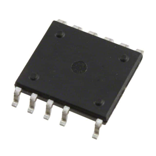
The reason is the pad. An eSOP-12B carries a large exposed thermal pad soldered straight to the board — and eleven leads, with pin 5 absent for creepage and pins 3 and 4 unused.
The SO-8C has an exposed pad too, but a much smaller one. That is where its 30°C/W junction-to-case figure comes from.
So the ranking inside this family is not through-hole first. It is large-pad surface mount, then through-hole, then small-pad surface mount — and the spread between the best and worst is 23W against 14.5W from identical silicon.
The catch is board area. An eSOP-12B footprint is wider than an SO-8C or a DIP-8C. On a densely packed adapter board that is the resource you were trying to save in the first place.
Naming that trade before the layout starts is cheaper than discovering it afterwards.
A Worked Replacement, With the Numbers
Take a TNY277GN design and move it to its TinySwitch-4 successor. Put the two sheets side by side and the swap is narrower than the package change suggests.
What stays identical: the standard current limit at 450mA, the maximum on-resistance at 9.0Ω cold and 13.5Ω hot, the open-frame peak rating at 23.5W, the 132kHz switching frequency, and the pinout.
What changes: the enclosed-adapter rating drops from 13W to 11.5W, the package goes from SMD-8C to SO-8C with an exposed pad, and the thermal path goes from 70°C/W to 100°C/W.
What you gain: the 725V breakdown voltage instead of 700V, and line-compensated overload power that holds the trip point within 15% across the input range instead of over 40%.
Now run your own number against it. At 11W inside a sealed case the move is comfortable and the extra de-rating never touches you.
At 12.5W you were inside the old row and outside the new one. Nothing on the board will tell you until thermal test.
How to Read a Switcher Power Table
Read the package column before the wattage column. Almost every surprise in this family disappears if you do those two things in that order.
Step 1 is the one that catches the TinySwitch case. When a product column reads "TNY288P/D/K" with one wattage behind it, all three packages share that rating. When it names them on separate rows, the number you read belongs to one package only.
Step 4 explains why the adapter row is the one that moves. It assumes a sealed, non-ventilated case measured at +50°C ambient, which is a thermal statement. The peak column is a capability statement, and it often survives a package change that the adapter row does not.
When to Design to the Package — and When Not To
Design to the package when the enclosure is sealed and the board is small. That is the case where the thermal path is the binding constraint, and where the difference between 70°C/W and 100°C/W decides whether the design passes or gets derated further.
Design to the die when the package is a manufacturing preference rather than a thermal one. If your copper area is generous and the enclosure has airflow, the surface-mount part and the DIP part converge, and the choice comes down to assembly.
And here is the case that makes the whole exercise worthwhile. If you need power and surface mount together, the answer is the eSOP-12B. It carries 23W from the same die where the SO-8C carries 14.5W, and it is still a reflow part.
What you are buying with the smaller package is board area. What you are paying is 1.5W per rung in the middle of the family, and a ceiling of 14.5W.
Internal Links
- TNY279GN — 18W TinySwitch-III, and why the SMD-8C version is not a derated part
- TNY277GN — the family's widest universal-input derating, and the swap paths out of it
- TNY288DG — TinySwitch-4 in SO-8C, with the thermal figure that explains the lower row
- TinySwitch-III vs TinySwitch-4 — four parts compared on the rows that decide
- TNY279GN pinout — the BP/M pin's three jobs and the layout mistakes that stop these supplies
- TNY279GN replacements — how the current limits interlock across the family
Frequently Asked Questions
Q1: Is TinySwitch-4 just TinySwitch-III with a higher voltage rating?
A: Electrically, at the same rung, yes — the limits and resistances are identical. What the newer family adds is the 725V breakdown, line-compensated overload power, a tighter undervoltage tolerance, and two additional packages. If you are comparing DIP to DIP at the same rung, the power rows match exactly.
Q2: Why does the SO-8C rate lower than the SMD-8C it replaces?
A: Because they are different packages with different thermal paths, and the newer sheet publishes both. TinySwitch-III's SMD-8C shares one thermal figure with its DIP version, so it inherits the DIP's power row. TinySwitch-4's SO-8C has its own figure at 100°C/W against the DIP's 70°C/W, so it gets its own, lower row.
Q3: At what power does the package start to matter?
A: From TNY287 upward in TinySwitch-4. At TNY284 through TNY286 the DIP and SO-8C rows are identical, so the package is a manufacturing choice. From TNY287 the SO-8C drops 1.5W below the DIP, and the gap is still there at TNY288.
Q4: Is there a surface-mount option that carries more than the SO-8C?
A: Yes — the eSOP-12B. The same TNY288 die rates 23W in eSOP-12B against 14.5W in SO-8C and 16W in DIP-8C. Its junction-to-air figure is 45°C/W, better than both. If you need power and surface mount together, that is the package.
Q5: Why is the peak column sometimes unchanged when the adapter column drops?
A: Because the two columns describe different limits. The adapter figure assumes a sealed, unventilated case at +50°C ambient, so it is thermally bounded. The peak column is a power-capability number. At TNY287 the adapter row drops to 11.5W while the peak row stays at 23.5W; at TNY288 both move.
Q6: Does the adapter row assume ventilation?
A: No — it assumes the opposite. The datasheet note behind it describes a typical non-ventilated enclosed adapter measured at +50°C ambient. If your enclosure has airflow or an external heatsink, the number improves, but you are then outside the printed row and measuring rather than reading.
Related information
-
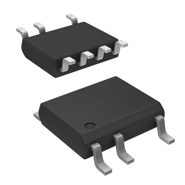
LNK304DN-TL Power Integrations
-
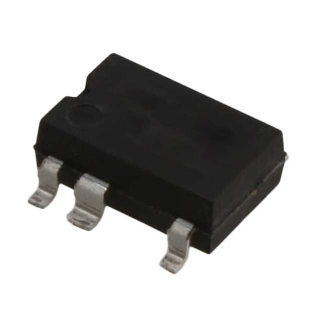
LNK304GN-TL Power Integrations
-
LNK304DG-TL Power Integrations
-
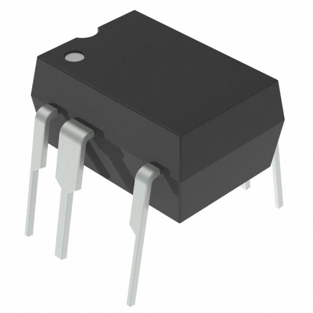
TNY277PN Power Integrations
-
TNY276PN Power Integrations
-
TNY278PN Power Integrations
-
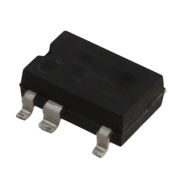
TNY278GN-TL Power Integrations
-
TNY280GN-TL Power Integrations
-
TOP266KG-TL Power Integrations
-
TOP258PN Power Integrations
-
TOP253PN Power Integrations
-
TOP253PNAU Power Integrations

- 1500+ Daily average RFQ Volume

- 20,000.000 Standard Product Unit

- 1800+ Worldwide Manufacturers

- 15,000+ In-stock Warehouse