


Infineon Technologies ESD200B1CSP0201XTSA1

- Part No.:
- ESD200B1CSP0201XTSA1
- Manufacturer:
- Infineon Technologies
- Category:
- TVS Diodes
- Package:
- 2-SMD, No Lead
- Datasheet:
-
 ESD200B1CSP0201XTSA1.pdf
- Description:
- TVS DIODE 5.5VWM 13VC
- Quantity:
-
Unit Price:$0
Ext Price:$0
- Payment:
-

- Shipping:
-


ESD200B1CSP0201XTSA1 Information
- Specifications
- Product Details
- Comparison
- Tags
- Product attributes
- Attribute value
- Manufacturer:
- Infineon Technologies
- Package/Case:
- 2-SMD, No Lead
- Series:
- -
- Packaging:
- Tape & Reel (TR)
- Product Status:
- Active
- Type:
- Zener
- Unidirectional Channels:
- -
- Bidirectional Channels:
- 1
- Voltage - Reverse Standoff (Typ):
- 5.5V (Max)
- Voltage - Breakdown (Min):
- 6V
- Voltage - Clamping (Max) @ Ipp:
- 13V (Typ)
- Current - Peak Pulse (10/1000µs):
- 16A (8/20µs)
- Power - Peak Pulse:
- -
- Power Line Protection:
- No
- Applications:
- General Purpose
- Capacitance @ Frequency:
- 6.5pF @ 1MHz
- Operating Temperature:
- -40°C ~ 125°C (TJ)
- Grade:
- -
- Qualification:
- -
- Mounting Type:
- Surface Mount
- Supplier Device Package:
- -
- Datasheet:
-
ESD200B1CSP0201XTSA1.pdf
ESD200-B1-CSP0201 — ±5.5V Bi-Directional ESD Protection Diode (CSP0201) from Infineon
The ESD200-B1-CSP0201 is a low-capacitance bi-directional ESD protection diode from Infineon in a 0.58 × 0.28mm CSP0201 package — one protected line, ±5.5V working voltage, 6.5pF capacitance, and a 13V clamp at 16A.
From what we see across Shenzhen module shipments (2025–2026), 0201-class ESD diodes ride on nearly every keypad, audio, and I2C line in consumer hardware. The field mistake we see most: putting a high-capacitance power TVS on a signal line, then chasing signal-integrity problems the protector itself caused.
6.5pF is the whole point. Small enough for low-speed signal lines, with a ±19kV ESD rating on top.
What Are the Technical Specifications of ESD200-B1-CSP0201?
| Parameter | Value |
|---|---|
| Type | Bi-directional TVS / ESD protection diode, 1 protected line |
| Reverse Working Voltage (VRWM) | ±5.5V max |
| Breakdown Voltage | 6V min / 10V max |
| Line Capacitance (CL) | 6.5pF typ @ 1MHz |
| Dynamic Resistance (RDYN) | 0.2Ω typ |
| Clamping Voltage (VCL) | 13V typ @ ITLP = 16A |
| Reverse Leakage (IR) | <1nA typ (100nA max) |
| Peak Pulse Current (IPP) | ±3A (8/20µs); peak pulse power 37.5W |
| ESD Rating (IEC61000-4-2) | ±19kV air / ±17kV contact |
| EFT Rating (IEC61000-4-4) | ±2kV / ±40A (5/50ns) |
| Package | WLL-2-1 (CSP0201), bottom terminals, marking "A" |
| Dimensions | 0.58 × 0.28 × 0.15 mm; 15,000 per reel |
| Operating Temperature | −55°C to +125°C |
Key numbers that matter: the 6.5pF is the selection driver — per the Infineon datasheet it keeps signal lines clean while still clamping at 13V with sub-nanoamp leakage. The ±19kV air discharge rating exceeds the IEC61000-4-2 class-4 requirement (15kV) with headroom to spare.
When Should You Use (and NOT Use) the ESD200-B1-CSP0201?
✅ Use ESD200-B1-CSP0201 when:
- Protecting low-speed signal lines. Keypads, GPIO, I2C, audio lines, touch controllers — the 6.5pF load is invisible below a few MHz.
- Board space is the constraint. The 0.58 × 0.28mm footprint takes less area than the via next to it — the smallest ESD protection that still carries a real IEC rating.
- Signals swing both polarities. Bi-directional audio and data lines need a symmetric clamp; this part clamps equally in both directions.
- Battery devices with leakage budgets. Sub-nanoamp leakage keeps coin-cell designs honest — no silent drain through the protector.
- Module-level integration. WiFi, fingerprint, flash, and camera modules ship with one per exposed line — the industrial qualification (JEDEC47/20/22) covers the full temperature range.
❌ Don't use ESD200-B1-CSP0201 when:
- Your line runs fast. USB 3.2 pairs need ≤0.5pF; HDMI 2.1 needs ≤0.25pF. At 6.5pF the capacitance rolls off the high-frequency content and closes the eye diagram — a guaranteed signal-integrity failure traded for a rare ESD event.
- Signal swing exceeds ±5.5V. A USB-C VBUS that reaches 20V under Power Delivery needs a TVS with a working voltage above the negotiated rail — this part would conduct on normal operation.
- You need real surge energy absorption. This is an ESD diode, not a surge device. Lightning and mains-coupled surges need a larger TVS (SMAJ-class) sized for the energy, not the capacitance.
- Power rails and hot-plug inputs. For bulk rail protection, a TVS with higher VRWM and a series fuse or resettable device does the job this part can't.
What Are the Alternatives to ESD200-B1-CSP0201?
| Model | Type | Key Difference | Best For |
|---|---|---|---|
| ESD5V3U2U-03 | Bi-directional ESD diode | SOD-323, similar rating, bigger package | Hand-solderable builds, same protection class |
| USBLC6-2SC6 | ESD array (2 lines + rail) | SOT-23-6, protects two lines with rail clamp | USB 2.0 and dual-line interfaces |
| ESD9L5.0 | Unidirectional ESD diode | SOD-923, 5V working, single polarity | Single-polarity 5V rails and GPIO |
| SMAJ5.0A | Power TVS | 400W surge class, high capacitance | Rail and input surge protection |
| Steering diode array | Discrete + rail TVS | Lower capacitance, but latch-up and overshoot risk | Legacy designs, signal speeds the ESD200 can't reach |
The decision in one line: capacitance first — slow lines and tiny boards → ESD200; dual-line → USBLC6-class array; surge energy → power TVS.
But why does capacitance beat raw protection power? Because a protector that distorts the signal fails on every transaction, while an ESD strike is rare — forum threads on "bigger is safer" TVS failures all trace back to skipping this first step.
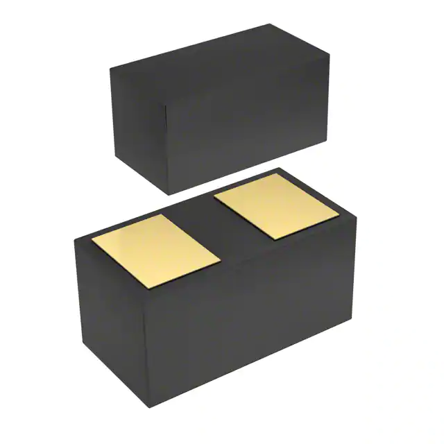
CSP0201 outline: a 0.58 × 0.28mm body with both terminals on the bottom face — no leads, no side pins. The "A" marking corner is the only orientation cue, and the pads sit directly under the body, so the part self-aligns in reflow.
Protection hookup: the diode shunts across the signal line to ground — normal data passes untouched, an ESD strike takes the 0.2Ω dynamic resistance path instead of the IC pin.
Place it as close to the connector as the board allows; every millimeter of trace before the diode adds inductance the clamp must overcome.
Line capacitance per interface — lower is better for speed:
6.5pF is fine below a few MHz and fatal at 10Gbps — that's the "bigger is safer" trap. What does that look like in practice?
A high-power TVS on a USB 3.2 pair rolls off the high-frequency content and closes the eye diagram — trading a rare ESD event for a guaranteed signal-integrity failure.
What Are the Typical Applications of ESD200-B1-CSP0201?
Keypad and button interfaces: one diode per row or column line, sized to fit the 0.3mm pitch these boards run. The 6.5pF load is irrelevant at key-scan speeds, and the ±19kV rating survives the human body model events that wreck unprotected scans.
I2C and GPIO buses in modules: WiFi modules, fingerprint sensors, and flash cards expose their lines at a connector edge — exactly where ESD arrives. A single CSP0201 per exposed line adds 6.5pF to a bus that tolerates tens of pF, and the sub-nanoamp leakage keeps the module's sleep budget intact.
Audio and headset lines: bi-directional clamping matters here — audio signals swing both polarities, and a unidirectional part would conduct on normal operation. The symmetric IV curve protects the codec input without loading the line the way a steering-diode array can.
Battery and wearable PCBs: at 0.58 × 0.28mm the diode fits where a SOD-323 won't — next to a micro-connector on a flex, inside a earbud stem, on a watch mainboard. It's the smallest protection that still carries a full IEC61000-4-2 rating.
Why Buy ESD200-B1-CSP0201 from ICMASS?
Capacitance and breakdown verified on incoming lots. We sample CL at 1MHz and VBR before shipment — a relabeled or wrong-grade ESD part shows up on the breakdown measurement, and mixed-reel leakage is the classic failure in this package class.
Cross-reference support for the whole ESD family. Not sure whether your line needs 6.5pF, a 2-line array, or a surge-class TVS? Send the interface speed, signal swing, and connector — we'll tell you which device the line actually needs, and keep the capacitance math straight.
BOM consolidation for module builders. The same board usually carries the MCU, a flash (W25Q-class), and ESD200 on the exposed lines — one shipment from Shenzhen covers the whole protection and storage section.
Same-day dispatch, 5–10 days worldwide. Orders before 15:00 CST ship same day via DHL or FedEx. For volume orders, we source directly from the Infineon production line.
Frequently Asked Questions About ESD200-B1-CSP0201
Q1: When do I need a bi-directional ESD diode?
A: When the signal swings both polarities. Audio lines, differential pairs, and any line that goes below ground in normal operation need a symmetric clamp. A unidirectional part conducts on the negative half of the swing and corrupts the signal — the Infineon community guidance is simply: single polarity → unidirectional, both polarities → bi-directional.
Q2: Why can't I use a bigger TVS on a high-speed line?
A: Capacitance — bigger protection means bigger junction area. A power TVS that handles surges carries tens of pF and rolls off high-frequency content. An Arduino forum thread on low-capacitance ESD diodes makes the tradeoff explicit, and high-speed interface budgets are unforgiving: USB 3.2 pairs need ≤0.5pF, HDMI 2.1 needs ≤0.25pF. "Bigger is safer" closes the eye diagram before the first ESD event ever happens.
Q3: What's the difference between breakdown and clamping voltage?
A: Breakdown is where conduction starts; clamping is what the IC actually sees. This part breaks down at 6–10V and clamps at 13V typ at 16A. During a real ESD pulse the clamped voltage can overshoot well above the spec — a StackExchange analysis notes high-current events can push a TVS to roughly 3× its rated clamp — so the margin between clamp and the IC's absolute maximum is what really decides survival.
Q4: Which lines can 6.5pF protect?
A: Everything below a few MHz. Keypads, GPIO, I2C, audio, touch, and slow sensor lines tolerate 6.5pF without measurable effect — the general rule from the Infineon community is that low-speed applications tolerate higher capacitance, while high-speed lines cannot.
Q5: Does leakage matter?
A: In precision or battery circuits, yes — and this part is built for that. Sub-nanoamp typ (100nA max) leakage keeps analog front-ends and coin-cell designs honest. An EEVblog thread on ADC input protection warns that ordinary clamp diodes leak "like a sieve" at 50°C and wreck precision measurements — the ESD200's leakage spec is the reason it belongs in those circuits.
Q6: How does it compare to a steering-diode array?
A: Simpler, more robust for a single line. Steering-diode arrays dump surge current into the power rail, which risks latch-up and needs an oversized decoupling cap; discrete steering diodes also aren't rated for ESD transient currents. A dedicated TVS per line clamps to ground, disturbs nothing else, and avoids the rail-dumping failure mode entirely — EEVblog threads recommend it whenever the signal level differs from the supplies.
Q7: Where on the board should it go?
A: As close to the connector as possible. Every millimeter of trace between the connector and the diode adds inductance the clamp must overcome, which shows up as overshoot during the pulse. The ideal placement is directly at the connector pin or within a few mm of it — and the CSP0201's tiny footprint is what makes that placement practical.
Q8: What do the ESD ratings mean?
A: They're the IEC61000-4-2 test levels the part survived. This part holds ±19kV air discharge and ±17kV contact discharge — above the class-4 level of 15kV that most product standards require. The rating tells you the diode survived; the clamp voltage tells you whether the IC behind it survived.
Q9: How do I solder a CSP0201?
A: Reflow only — the terminals are on the bottom face. The 0.58 × 0.28mm body with bottom pads is not hand-solderable in practice; it needs a stencil, solder paste, and a reflow profile. The "A" marking corner is the orientation cue. For prototype or hand-assembly work, pick the SOD-323 alternative instead.
Q10: How do I choose the working voltage (VRWM)?
A: Above the highest normal signal voltage on the line. A 3.3V logic line fits a ±5.5V part comfortably. But a USB-C VBUS that negotiates 20V under Power Delivery needs a TVS with a working voltage above 20V — otherwise the protector conducts during normal operation and kills the line it was meant to save.
| Image |
|
| Part Number | ESD200B1CSP0201XTSA1 |
| Manufacturer | Infineon Technologies |
| Package/Case | 2-SMD, No Lead |
| Series | - |
| Packaging | Tape & Reel (TR) |
| Product Status | Active |
| Type | Zener |
| Unidirectional Channels | - |
| Bidirectional Channels | 1 |
| Voltage - Reverse Standoff (Typ) | 5.5V (Max) |
| Voltage - Breakdown (Min) | 6V |
| Voltage - Clamping (Max) @ Ipp | 13V (Typ) |
| Current - Peak Pulse (10/1000µs) | 16A (8/20µs) |
| Power - Peak Pulse | - |
| Power Line Protection | No |
| Applications | General Purpose |
| Capacitance @ Frequency | 6.5pF @ 1MHz |
| Operating Temperature | -40°C ~ 125°C (TJ) |
| Grade | - |
| Qualification | - |
| Mounting Type | Surface Mount |
| Supplier Device Package | - |
User Guide
- Purchase & Inquiry
- Package
- Shipping Information
- Customer Review
You may place an order without registering to IC-MAX.COM
We strongly suggest you sign in before purchasing as you can track your order in real time.
For your convenience, we accept multiple payment methods in USD, including PayPal, Credit Card, and wire transfer.
RFQ (Request for Quotations)
It is recommended to request for quotations to get the latest prices and inventories about the part.
Our sales will reply to your request by email within 24 hours.
1. You'll receive an order information email in your inbox. (Please remember to check the spam folder if you didn't hear from us).
2. Since inventories and prices may fluctuate to some extent, the sales manager is going to reconfirm the order and let you know if there are any updates.
-

- Step1:Prepare product
-

- Step2:Vacuum packaging
-

- Step3:Anti-static bag
-

- Step4:Individual package
-

- Step5:Packaging box
-

- Step6:Barcode shipping label
Shipping starts at $40, but some countries will exceed $40. For example (South Africa, Brazil, India, Pakistan, Israel, etc.)
The basic freight (for package ≤0.5kg or corresponding volume) depends on the time zone and country.
Currently, our products are shipped through DHL, FedEx, SF, and UPS.
Delivery TimeOnce the goods are shipped, estimated delivery time depends on the shipping methods you chose:
FedEx International, 5-7 business days.
The following are some common countries' logistic time.

- Hot Sale
- Related Categories
- Include Parts
- Popular Search
The following parts include "ESD200B1CSP0201XTSA1" in Silicon Labs ESD200B1CSP0201XTSA1.
- Part Number
- Manufacturer
- Package
- Description
- ESD9B5.0ST5G onsemi 2-SMD, No Lead TVS DIODE 5.5VWM 13VC
- DESD3V3E1BL-7B Diodes Incorporated 2-SMD, No Lead TVS DIODE 5.5VWM 13VC
- ESD5Z3.3T1G onsemi 2-SMD, No Lead TVS DIODE 5.5VWM 13VC
- D5V0H1B2LP-7B Diodes Incorporated 2-SMD, No Lead TVS DIODE 5.5VWM 13VC
- D5V0P1B2LP-7B Diodes Incorporated 2-SMD, No Lead TVS DIODE 5.5VWM 13VC
- DESD5V0U1BA-7 Diodes Incorporated 2-SMD, No Lead TVS DIODE 5.5VWM 13VC
- ESD5Z5.0T1G onsemi 2-SMD, No Lead TVS DIODE 5.5VWM 13VC
- DESD5V0U1BB-7 Diodes Incorporated 2-SMD, No Lead TVS DIODE 5.5VWM 13VC
- D12V0L1B2LP-7B Diodes Incorporated 2-SMD, No Lead TVS DIODE 5.5VWM 13VC
- PESD2V0Y1BSFYL Nexperia USA Inc. 2-SMD, No Lead TVS DIODE 5.5VWM 13VC
The following parts are popular search parts in Test and Measurement.
Inventory:76,922
Please send an inquiry. Send us your inquiry, and we will respond immediately.

- 1500+ Daily average RFQ Volume

- 20,000.000 Standard Product Unit

- 1800+ Worldwide Manufacturers

- 15,000+ In-stock Warehouse


