NCEPower NCE603S

- Part No.:
- NCE603S
- Manufacturer:
- NCEPower
- Category:
- MOSFET
- Package:
- Description:
- The NCE603S puts a 60 V N-channel and a 60 V P-channel in one SOP-8L package. The N side is rated 5 A with 28 mΩ maximum on-resistance at 10 V. The P side is rated 4 A with 80 mΩ .
- Quantity:
-
Unit Price:$0
Ext Price:$0
- Payment:
-

- Shipping:
-


NCE603S Information
- Specifications
- Product Details
- Comparison
- Tags
- Product attributes
- Attribute value
- Manufacturer:
- NCEPower
- Package:
- SOP-8
- Part Status:
- Production
- Car grade industrial grade:
- Industrial grade
- Technology:
- Trench
- Polarity:
- N+P
- BVDSS(V):
- -60
- ID(A):
- -6
- VTH(V):
- -2.6
- RDS(ON)@10VTyp(mΩ):
- 64
- RDS(ON)@10VMax(mΩ):
- 80
- RDS(ON)@4.5VTyp(mΩ):
- RDS(ON)@4.5VMax(mΩ):
- RDS(ON)@2.5VTyp(mΩ):
- RDS(ON)@2.5VMax(mΩ):
- VGS(th)(V):
- ±20
- CISS(pF):
- 1450
- QG(nC):
- 26
- PD(W):
- 2
- Specialfeature:
The NCE603S puts a 60 V N-channel and a 60 V P-channel in one SOP-8L package. The N side is rated 5 A with 28 mΩ maximum on-resistance at 10 V. The P side is rated 4 A with 80 mΩ.
That is a 2.86x resistance gap between two channels that share a package, a thermal path, and one datasheet. But the two resistance rows aren't measured at the same current, so the ratio isn't clean.
We stock the SOP-8L reel for H-bridge and inverter builds, and the P side is the one that sets the thermal budget.
How Do the N and P Channels Compare?
The P channel is the weaker side on every row that matters. On-resistance is 80 mΩ against 28 mΩ, gate charge is 50 nC against 22 nC, and input capacitance is 2693 pF against 979 pF.
Switching follows the same pattern. Fall time is 11 ns on the P side and 2 ns on the N side, a 5.5x gap. In a bridge, the slower side sets the dead time you have to allow.
But why does the P side cost so much more?
A P-channel needs more die area for the same resistance, and this one is built for 4 A instead of 5 A. The 2.86x is real, but it compares 5 A on one side with 4 A on the other.
What Happens When Both Channels Run at Once?
At their own rated currents, the two channels dissipate 1.98 W together. The N side contributes 0.70 W and the P side contributes 1.28 W.
The datasheet gives 2 W per channel at 25 °C ambient, with a 62.5 °C/W junction-to-ambient path. There is no row for both channels conducting.
So the pair lands at 99% of a rating written for one channel. At 25 °C ambient, the junction rise is 124 °C against a 150 °C limit.
An H-bridge does exactly this: one N and one P conduct on each diagonal. The package sees both losses, not one.
That doesn't mean the part fails. It means 2 W isn't a 4 W budget. Treat it as the package total and split it between the two channels.
Is the 2.86x Resistance Ratio a Fair Comparison?
No. The N row is tested at 5 A and the P row at 4 A, and the P side has no 4.5 V row at all.
The missing 4.5 V row matters more than the ratio. If your gate drive is 4.5 V, the N side has a guaranteed 38 mΩ maximum. The P side has nothing.
| Row | N channel | P channel |
|---|---|---|
| RDS at 10 V | 24 typ / 28 max mΩ | 64 typ / 80 max mΩ |
| Test current | 5 A | 4 A |
| RDS at 4.5 V | 32 typ / 38 max mΩ | No row |
| Threshold | 1.0 to 2.5 V | -1.5 to -3.0 V |
| Gate charge | 22 nC | 50 nC |
| Input capacitance | 979 pF | 2693 pF |
The P threshold is −1.5 to −3.0 V, so a 4.5 V drive leaves 1.5 V of overdrive at worst case. The N side gets 2.0 V.
So how should you compare them? At the drive you'll actually use, not at the headline currents.
Bars are scaled so 125 °C fills the track. The pair uses 99% of it before you add any copper beyond the test board.
What Are the Specifications of NCE603S?
A 60 V complementary pair in SOP-8L: 5 A N-channel and 4 A P-channel, both rated 2 W at 25 °C ambient. Rows are from the NCE NCE603S datasheet, v6.0.
| Parameter | N channel | P channel |
|---|---|---|
| Drain-source voltage | 60 V | -60 V |
| Gate-source voltage | ±20 V | ±20 V |
| Continuous drain current at 25 °C | 5 A | -4 A |
| Continuous drain current at 100 °C | 3.5 A | -2.8 A |
| Pulsed drain current | 30 A | -30 A |
| Power dissipation at 25 °C | 2 W | 2 W |
| Junction-to-ambient | 62.5 °C/W | 62.5 °C/W |
| Junction-to-lead | 30 °C/W | 30 °C/W |
| Gate threshold | 1.0 / 1.6 / 2.5 V | -1.5 / -2.6 / -3.0 V |
| RDS at 10 V | 24 / 28 mΩ at 5 A | 64 / 80 mΩ at -4 A |
| RDS at 4.5 V | 32 / 38 mΩ at 5 A | No row |
| Input / output / reverse capacitance | 979 / 120 / 100 pF | 2693 / 107 / 95 pF |
| Total gate charge | 22 nC | 50 nC |
| Turn-on delay / rise | 4.2 / 3.4 ns | 9 / 10 ns |
| Turn-off delay / fall | 16 / 2 ns | 25 / 11 ns |
| Body diode forward voltage | 1.2 V typ at 5 A | -1.2 V typ at -4 A |
| Reverse recovery time / charge | 27 ns / 30 nC | 27.5 ns / 30 nC |
| Junction temperature range | -55 to 150 °C | -55 to 150 °C |
Two numbers to carry. The 2 W is per channel, and the P side has no 4.5 V resistance row.
When Should You Use (and NOT Use) the NCE603S?
Use it when one SOP-8L has to hold both halves of a 60 V bridge, and the high side can take 4 A.
Use the NCE603S when:
- Your rail is up to 60 V
- The N side carries up to 5 A and the P side up to 4 A
- Both gates are driven at 10 V
- You can spread about 2 W across the package and the board
- You want one package instead of two
Don't use the NCE603S when:
- You need a guaranteed P-channel RDS at 4.5 V; there is no row
- The high side must carry more than 4 A
- Both channels run near rating with no copper beyond the minimum pad
- You need a low-threshold logic-level pair
Why Buy NCE603S from ICMASS?
Because the pair is usually chosen for the N side and paid for on the P side. We stock the SOP-8L reel and can check the P-channel rows against your drive.
At rated current the pair dissipates 1.98 W, and 1.28 W of that is the P side. The N side is 0.70 W.
Tell us your rail, your drive, and your current. We'll tell you which rows apply and which ones don't exist.
Frequently Asked Questions About NCE603S
Q1: What is the NCE603S?
A: A 60 V complementary N-channel and P-channel MOSFET pair in one SOP-8L. The N side is rated 5 A at 28 mΩ maximum, the P side 4 A at 80 mΩ, both 2 W at 25 °C.
Q2: Why is the P-channel resistance higher?
A: It is 80 mΩ against 28 mΩ, a 2.86x gap. The rows are tested at 4 A and 5 A respectively, so the ratio includes a different test point.
Q3: Can I drive the P channel from 4.5 V?
A: There is no guaranteed row for it. The only P-channel RDS row is at -10 V, 80 mΩ maximum. The threshold runs to -3.0 V, leaving 1.5 V of overdrive at 4.5 V.
Q4: What do both channels dissipate at rated current?
A: 1.98 W total: 0.70 W on the N side and 1.28 W on the P side. That is 99% of the 2 W per-channel rating.
Q5: Is the 2 W rating per channel or total?
A: The sheet prints 2 W per channel at 25 °C ambient, and there is no combined row. Treat 2 W as the package total when both channels conduct.
Q6: What junction temperature does 1.98 W produce?
A: 124 °C of rise from 25 °C ambient through 62.5 °C/W, giving 149 °C against a 150 °C limit.
Q7: What is the gate charge on each side?
A: 22 nC on the N side and 50 nC on the P side, both at 10 V. The P side also has 2693 pF of input capacitance against 979 pF.
Q8: What package and reel does it use?
A: SOP-8L in a 4000-unit reel with 12 mm tape. The package is 4.7 to 5.1 mm long by 3.8 to 4.0 mm wide.
| Image |

|
| Part Number | NCE603S |
| Manufacturer | NCEPower |
| Package | SOP-8 |
| Part Status | Production |
| Car grade industrial grade | Industrial grade |
| Technology | Trench |
| Polarity | N+P |
| BVDSS(V) | -60 |
| ID(A) | -6 |
| VTH(V) | -2.6 |
| RDS(ON)@10VTyp(mΩ) | 64 |
| RDS(ON)@10VMax(mΩ) | 80 |
| RDS(ON)@4.5VTyp(mΩ) | |
| RDS(ON)@4.5VMax(mΩ) | |
| RDS(ON)@2.5VTyp(mΩ) | |
| RDS(ON)@2.5VMax(mΩ) | |
| VGS(th)(V) | ±20 |
| CISS(pF) | 1450 |
| QG(nC) | 26 |
| PD(W) | 2 |
| Specialfeature |
User Guide
- Purchase & Inquiry
- Package
- Shipping Information
- Customer Review
You may place an order without registering to IC-MAX.COM
We strongly suggest you sign in before purchasing as you can track your order in real time.
For your convenience, we accept multiple payment methods in USD, including PayPal, Credit Card, and wire transfer.
RFQ (Request for Quotations)
It is recommended to request for quotations to get the latest prices and inventories about the part.
Our sales will reply to your request by email within 24 hours.
1. You'll receive an order information email in your inbox. (Please remember to check the spam folder if you didn't hear from us).
2. Since inventories and prices may fluctuate to some extent, the sales manager is going to reconfirm the order and let you know if there are any updates.
-
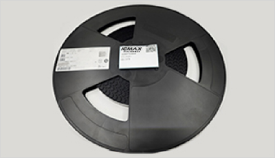
- Step1:Prepare product
-
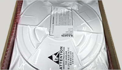
- Step2:Vacuum packaging
-
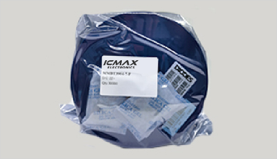
- Step3:Anti-static bag
-
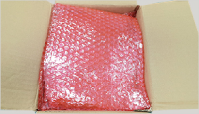
- Step4:Individual package
-
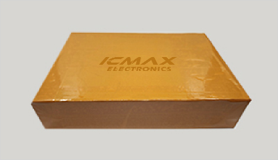
- Step5:Packaging box
-
- Step6:Barcode shipping label
Shipping starts at $40, but some countries will exceed $40. For example (South Africa, Brazil, India, Pakistan, Israel, etc.)
The basic freight (for package ≤0.5kg or corresponding volume) depends on the time zone and country.
Currently, our products are shipped through DHL, FedEx, SF, and UPS.
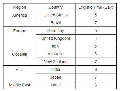
Delivery TimeOnce the goods are shipped, estimated delivery time depends on the shipping methods you chose:
FedEx International, 5-7 business days.
The following are some common countries' logistic time.
- Hot Sale
- Related Categories
- Include Parts
- Popular Search
The following parts include "NCE603S" in Silicon Labs NCE603S.
- Part Number
- Manufacturer
- Package
- Description
- NCE2301C Industrial grade The NCE603S puts a 60 V N-channel and a 60 V P-channel in one SOP-8L package. The N side is rated 5 A with 28 mΩ maximum on-resistance at 10 V. The P side is rated 4 A with 80 mΩ .
- NCE2301A Industrial grade The NCE603S puts a 60 V N-channel and a 60 V P-channel in one SOP-8L package. The N side is rated 5 A with 28 mΩ maximum on-resistance at 10 V. The P side is rated 4 A with 80 mΩ .
- NCE3417 Industrial grade The NCE603S puts a 60 V N-channel and a 60 V P-channel in one SOP-8L package. The N side is rated 5 A with 28 mΩ maximum on-resistance at 10 V. The P side is rated 4 A with 80 mΩ .
- NCE1013E* Industrial grade The NCE603S puts a 60 V N-channel and a 60 V P-channel in one SOP-8L package. The N side is rated 5 A with 28 mΩ maximum on-resistance at 10 V. The P side is rated 4 A with 80 mΩ .
- NCE2301D Industrial grade The NCE603S puts a 60 V N-channel and a 60 V P-channel in one SOP-8L package. The N side is rated 5 A with 28 mΩ maximum on-resistance at 10 V. The P side is rated 4 A with 80 mΩ .
- NCE2301F Industrial grade The NCE603S puts a 60 V N-channel and a 60 V P-channel in one SOP-8L package. The N side is rated 5 A with 28 mΩ maximum on-resistance at 10 V. The P side is rated 4 A with 80 mΩ .
- NCE2301B Industrial grade The NCE603S puts a 60 V N-channel and a 60 V P-channel in one SOP-8L package. The N side is rated 5 A with 28 mΩ maximum on-resistance at 10 V. The P side is rated 4 A with 80 mΩ .
- NCE2301E* Industrial grade The NCE603S puts a 60 V N-channel and a 60 V P-channel in one SOP-8L package. The N side is rated 5 A with 28 mΩ maximum on-resistance at 10 V. The P side is rated 4 A with 80 mΩ .
- NCE2301 Industrial grade The NCE603S puts a 60 V N-channel and a 60 V P-channel in one SOP-8L package. The N side is rated 5 A with 28 mΩ maximum on-resistance at 10 V. The P side is rated 4 A with 80 mΩ .
- NCE2321 Industrial grade The NCE603S puts a 60 V N-channel and a 60 V P-channel in one SOP-8L package. The N side is rated 5 A with 28 mΩ maximum on-resistance at 10 V. The P side is rated 4 A with 80 mΩ .
The following parts are popular search parts in Test and Measurement.
Inventory:50,000
Please send an inquiry. Send us your inquiry, and we will respond immediately.

- 1500+ Daily average RFQ Volume

- 20,000.000 Standard Product Unit

- 1800+ Worldwide Manufacturers

- 15,000+ In-stock Warehouse