NPN vs PNP Transistor: Key Differences & How to Choose
NPN vs PNP Transistor: Key Differences & How to Choose
The short answer: NPN transistors switch the low side (between load and ground). PNP transistors switch the high side (between supply and load). If you're driving a load from a microcontroller GPIO, start with an NPN. If you need to switch the supply rail to a load, you need a PNP.
But the real question isn't "which is better?" — it's "which configuration does your circuit need?" NPNs are faster and cheaper because electrons move through silicon more easily than holes. That's why NPNs outnumber PNPs in most designs by roughly 5:1. But PNPs aren't going anywhere — they're essential for high-side switching, complementary push-pull amplifiers, and LDO regulator pass elements.
From our Shenzhen distribution data (2025–2026), NPN transistors (2N3904, 2N2222, S8050, BC547) outsell PNP equivalents (2N3906, 2N2907, S8550, BC557) by about 4:1 in volume. But engineers who need PNPs need them specifically — you can't just drop an NPN into a high-side switch position and expect it to work.
NPN vs PNP: Quick Comparison Table
| Parameter | NPN | PNP |
|---|---|---|
| Structure | N-P-N (P-type base between two N-type layers) | P-N-P (N-type base between two P-type layers) |
| Majority Carrier | Electrons (faster — ~2–3× higher mobility) | Holes (slower) |
| Symbol Arrow | Points OUT from base to emitter | Points IN toward base from emitter |
| Turn-On Condition | Base ~0.7V above emitter (positive VBE) | Base ~0.7V below emitter (negative VBE) |
| To Turn ON | Apply positive voltage to base (relative to emitter) | Pull base LOW (ground or negative relative to emitter) |
| Current Flow (On State) | Collector → Emitter | Emitter → Collector |
| Switching Speed | Faster (electron mobility advantage) | Slower (hole mobility limitation) |
| Switching Configuration | Low-side switch (load to VCC, transistor to GND) | High-side switch (transistor to VCC, load to GND) |
| Typical GPIO Drive | GPIO HIGH → transistor ON (simple, direct) | GPIO LOW → transistor ON (may need level shifting to turn OFF) |
| Common Applications | LED drivers, relay drivers, logic switching, amplification | High-side load switching, push-pull output stages, LDO pass elements |
| Cost | Lower | Slightly higher (less volume production) |
| Availability | Wider selection, more second sources | Fewer options, but common types well-stocked |
| Common Part Numbers | 2N3904, 2N2222, BC547, S8050, MMBT3904 | 2N3906, 2N2907, BC557, S8550, MMBT3906 |
Why NPN Transistors Dominate (And Why PNPs Still Matter)
The physics gives NPNs a built-in advantage. In an NPN transistor, the majority carriers are electrons — which move through silicon roughly 2–3× faster than holes, the majority carriers in PNP transistors. This translates directly to higher switching speed, higher gain (hFE) at equivalent sizes, and better high-frequency performance.
For most microcontroller-driven switching tasks, NPNs are also easier to design with. Your MCU GPIO goes high (3.3V or 5V), current flows through a base resistor into the NPN base, and the transistor saturates. The load sits between VCC and the collector. If something goes wrong — the GPIO floats, power glitches — the NPN turns off. Fail-safe.
But PNPs own one critical use case: switching the supply side of a load. When you need to connect or disconnect a load from VCC (rather than from ground), a PNP is the natural choice. Think battery-powered devices where you want to kill power to an entire subsystem, or load switches where the load must remain at ground potential when off. You can do high-side switching with an NPN, but it requires a gate-drive voltage above the supply rail — messy. The PNP does it with a simple pull-down on the base.
Low-Side vs High-Side Switching: The Real Decision Point
Most "NPN vs PNP" questions are secretly "low-side vs high-side switching" questions. Here's the framework:
| Configuration | Transistor Type | How It Works | Best For |
|---|---|---|---|
| Low-Side Switch | NPN | Load connected to VCC. NPN sits between load and GND. GPIO HIGH = ON. | LEDs, relays, solenoids, most MCU-driven loads |
| High-Side Switch | PNP | PNP sits between VCC and load. Load connected to GND. GPIO LOW = ON. | Power rail switching, battery disconnect, load isolation |
The PNP Trap: Turning It OFF Requires Base at Emitter Voltage
This catches beginners constantly. An NPN turns on when its base is ~0.7V above the emitter (which is grounded). Simple — a 3.3V GPIO drives it easily. To turn it off, you just drive the GPIO low.
A PNP turns on when its base is ~0.7V below the emitter (which is at VCC). To turn it off, the base must rise to VCC. If your MCU runs at 3.3V but VCC is 12V, your GPIO can pull the base low enough to turn the PNP on — but it cannot raise the base to 12V to turn it off. The transistor stays on. The fix: add an NPN to pull the PNP's base to VCC when the GPIO goes low. This two-transistor configuration (NPN driving PNP) is the standard high-side switch pattern and it appears in basically every circuit that uses a PNP as a load switch.
When to Use NPN
- You're switching a load from a microcontroller GPIO (3.3V or 5V logic): NPN + base resistor + load to VCC. It works, it's cheap, and it fails safe (GPIO floating = transistor off).
- You need speed: electrons beat holes every time. For PWM, fast digital switching, or high-frequency amplification, NPN is the default.
- You're building a low-side current sink: LED constant-current drivers, relay coil drivers, solenoid drivers. The load naturally references the positive rail; the NPN switches the return path.
- Cost and availability matter: NPNs are produced in higher volumes, second-sourced by more manufacturers, and stocked in more variants. If you don't know which to pick, pick an NPN.
When to Use PNP
- You need to switch the supply side (high-side switching): the load must stay grounded, and you want to connect/disconnect it from VCC. PNP is the clean solution.
- Battery-powered load disconnect: you want to kill power to an entire subsystem to save battery. A PNP high-side switch disconnects the load completely — no leakage path through a grounded load.
- Complementary push-pull output stage: Class B and AB amplifiers use an NPN for the positive half-cycle and a PNP for the negative half-cycle. You need both.
- LDO voltage regulator pass element: many LDOs use a PNP (or P-channel MOSFET) as the series pass transistor because it allows lower dropout voltage than an NPN-based design.
- Industrial sensors (regional preference): in factory automation, "PNP sensors" (sourcing output) are standard in Europe and North America. They produce a positive output signal when active and are safer — if the signal wire frays to ground, the sensor reads "off" rather than "on." NPN sensors (sinking output) are more common in Asia.
Common NPN/PNP Confusions (And Their Answers)
"Can I just use NPNs for everything?"
You can — with a topology trick. An NPN can do high-side switching if you drive its base with a voltage above the supply rail (a bootstrap or charge pump). But that's extra circuitry. The PNP does high-side switching with one transistor and a resistor. Engineering is about picking the right tool for the job, not proving you can do everything with a hammer.
"Can I convert a PNP circuit to NPN?"
Not by swapping the transistor. You need to redesign the circuit: flip the supply polarity, move the load from the collector side to the emitter side, and invert the control logic. The PCB layout changes, the control signal polarity flips, and the fail-safe behavior reverses. Sometimes it's worth it (if you're standardizing on NPNs for cost). Most of the time, just use the PNP.
"How do I identify whether an unknown transistor is NPN or PNP?"
Use a multimeter in diode mode. For NPN: red probe on base, black on emitter → ~0.6–0.7V drop. Red on base, black on collector → same. Reverse the probes → open circuit. For PNP: black probe on base, red on emitter → ~0.6–0.7V. Black on base, red on collector → same. The base-emitter and base-collector junctions are diodes; the polarity of those diodes tells you NPN vs PNP.
Pricing & Availability
| Type | Popular Part Numbers | Package | Price Reference (volume) | Availability |
|---|---|---|---|---|
| NPN Small-Signal | 2N3904, BC547, S8050, MMBT3904 | TO-92, SOT-23 | $0.008–0.02/unit | Widely stocked |
| PNP Small-Signal | 2N3906, BC557, S8550, MMBT3906 | TO-92, SOT-23 | $0.01–0.025/unit | Well stocked |
| NPN Medium-Power | 2N2222, BD139, TIP41 | TO-92, TO-126, TO-220 | $0.02–0.15/unit | Widely stocked |
| PNP Medium-Power | 2N2907, BD140, TIP42 | TO-92, TO-126, TO-220 | $0.03–0.20/unit | Well stocked |
Contact ICMASS for current pricing on your specific part number and quantity. We stock the full range of NPN and PNP transistors — small-signal, medium-power, and power — with traceability to ON Semi, Nexperia, Diodes Inc, and other major manufacturers. Ship from Shenzhen.
Frequently Asked Questions About NPN vs PNP Transistors
Q1: What is the main difference between NPN and PNP transistors?
A: NPN transistors turn on with a positive base voltage (~0.7V above emitter) and conduct current from collector to emitter. They're used for low-side switching (between load and ground). PNP transistors turn on with a negative/low base voltage (~0.7V below emitter) and conduct current from emitter to collector. They're used for high-side switching (between supply and load). The physics difference: NPN majority carriers are electrons (faster); PNP majority carriers are holes (slower).
Q2: When should I use NPN instead of PNP?
A: Use NPN when: driving loads from a microcontroller GPIO (low-side switching), you need high switching speed, cost is a primary concern, or you're building the most common transistor circuits (LED drivers, relay drivers, logic-level switching). NPN is the default choice in most designs — start there and switch to PNP only when the topology demands it.
Q3: When is a PNP transistor the right choice?
A: Use PNP when you need high-side switching (connecting/disconnecting a load from VCC), battery-powered load disconnect, complementary push-pull amplifier output stages, LDO regulator pass elements, or in industrial sensors where sourcing output (PNP) is the regional standard. You can't easily replace a PNP with an NPN in these applications without redesigning the circuit topology.
Q4: Can I directly replace an NPN with a PNP (or vice versa)?
A: No. They are fundamentally different devices with opposite polarity. Swapping one for the other requires redesigning the circuit: flipping supply polarity, moving the load from collector to emitter (or vice versa), and inverting the control logic. A direct part-for-part swap will not work and may damage the transistor or downstream components.
Q5: Why can't I turn off my PNP transistor when using a 3.3V MCU with a 12V supply?
A: This is the most common PNP beginner trap. To turn a PNP off, the base must rise to the emitter voltage (which is at VCC = 12V). Your 3.3V GPIO can only go up to 3.3V — nowhere near 12V. The PNP stays on. The fix: use an NPN transistor to pull the PNP's base to VCC. The NPN's collector connects to the PNP's base through a resistor; the NPN's base is driven by your GPIO. GPIO HIGH → NPN ON → PNP base pulled low → PNP ON. GPIO LOW → NPN OFF → PNP base rises to VCC through pull-up → PNP OFF.
Q6: How do I identify whether an unknown transistor is NPN or PNP with a multimeter?
A: Use diode test mode. Find the base first (the pin that shows ~0.6–0.7V to the other two pins). If the red probe on base shows ~0.6–0.7V to the other pins (black on emitter/collector), it's NPN. If the black probe on base shows ~0.6–0.7V (red on emitter/collector), it's PNP. The base-emitter and base-collector junctions are diodes; the polarity of those diodes reveals the transistor type.
Q7: Are NPN transistors cheaper than PNP?
A: Yes, slightly. NPNs are manufactured in higher volume (roughly 4–5:1 vs PNP equivalents) and have a simpler manufacturing process for the same performance level. A 2N3904 (NPN) typically costs $0.008–0.015/unit in volume, while a 2N3906 (PNP equivalent) runs $0.01–0.02/unit. The difference is small in absolute terms but adds up across a BOM.
Related information
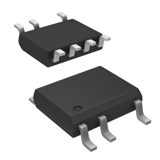
-
LNK304DN-TL Power Integrations
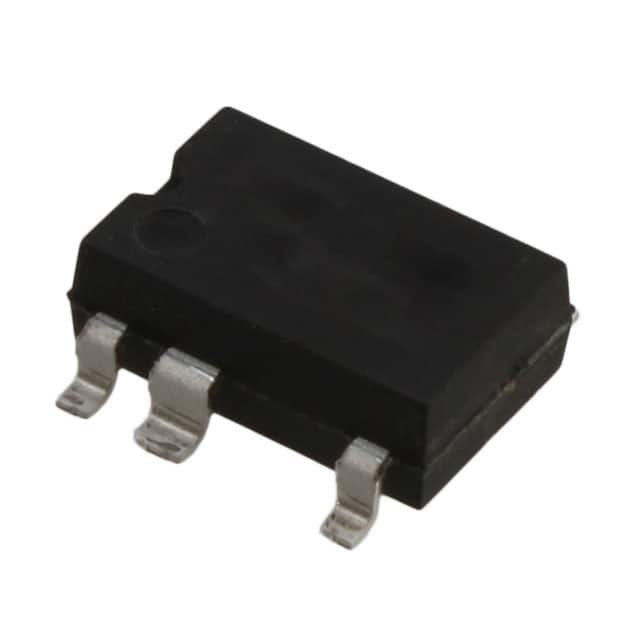
-
LNK304GN-TL Power Integrations
-
LNK304DG-TL Power Integrations
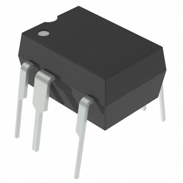
-
TNY277PN Power Integrations
-
TNY276PN Power Integrations
-
TNY278PN Power Integrations
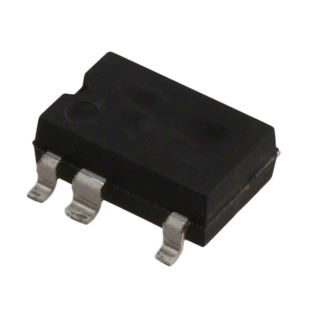
-
TNY278GN-TL Power Integrations
-
TNY280GN-TL Power Integrations
-
TOP266KG-TL Power Integrations
-
TOP258PN Power Integrations
-
TOP253PN Power Integrations
-
TOP253PNAU Power Integrations

- 1500+ Daily average RFQ Volume

- 20,000.000 Standard Product Unit

- 1800+ Worldwide Manufacturers

- 15,000+ In-stock Warehouse