IRF540NPBF vs IRF640NPBF vs IRFZ44NPBF — Which TO-220 Power MOSFET Should You Choose?
Quick Summary
Pick IRFZ44NPBF for 12V/24V high-current designs (17.5mΩ max RDS(on), 49A, $0.42/1k). Pick IRF540NPBF for 24V/48V systems (44mΩ, 33A, $0.55/1k). Pick IRF640NPBF for 48V-72V high-voltage applications (150mΩ, 18A, $0.65/1k). These three parts span the voltage-resistance trade-off in Infineon's TO-220 HEXFET family.
How Do IRF540NPBF, IRF640NPBF, and IRFZ44NPBF Compare on Key Parameters?
| Parameter | IRFZ44NPBF | IRF540NPBF | IRF640NPBF |
|---|---|---|---|
| VDS (max) | 55V | 100V | 200V |
| ID cont. (25°C case) | 49A | 33A | 18A |
| ID cont. (100°C case) | 35A | 23A | 13A |
| ID pulsed | 160A | 110A | 72A |
| RDS(on) max @ 10Vgs | 17.5mΩ | 44mΩ | 150mΩ |
| RDS(on) typ @ 10Vgs | 13.5mΩ | 35mΩ | 115mΩ |
| Qg total @ 10V | 63nC | 71nC | 67nC |
| Ciss | 1470pF | 1960pF | 1160pF |
| Crss | 88pF | 40pF | 53pF |
| EAS (Avalanche) | 260mJ | 200mJ | 130mJ |
| PD (25°C case) | 94W | 130W | 150W |
| θJC | 1.5°C/W | 1.15°C/W | 1.0°C/W |
| trr | 95ns | ~100ns | 170ns |
| Package | TO-220AB | TO-220AB | TO-220AB |
| Price (1k) | $0.42 | $0.55 | $0.65 |
What Is the Voltage vs Resistance Trade-Off in These MOSFETs?
Higher voltage rating requires a thicker, more lightly doped drift region, which increases on-resistance. The IRFZ44NPBF (55V) has 17.5mΩ max. Doubling the voltage to 100V (IRF540N) raises RDS(on) to 44mΩ (2.5×). Going to 200V (IRF640N) raises it to 150mΩ (8.6×).
Choose the lowest voltage rating that provides adequate safety margin above your system's peak operating voltage plus transients. Higher voltage always means more heat at the same current.
What Is the Thermal Performance of Each MOSFET at Various Currents?
All calculations use typical RDS(on) and a standard clip-on heatsink (θSA 25°C/W) at 25°C ambient.
At 10A Load
| Part | Power | Junction Temp | Verdict |
|---|---|---|---|
| IRFZ44NPBF | 1.35W | 61°C | ✅ Cool |
| IRF540NPBF | 3.5W | 118°C | ⚠️ Warm |
| IRF640NPBF | 11.5W | 330°C | ❌ Requires bolt-on heatsink |
At 20A Load
| Part | Power | Junction Temp | Verdict |
|---|---|---|---|
| IRFZ44NPBF | 5.4W | 171°C | ⚠️ Near limit |
| IRF540NPBF | 14W | - | ❌ Exceeds max |
| IRF640NPBF | 46W | - | ❌ Impossible |
Are These Three MOSFETs Pin-Compatible?
Yes. All three use the standard TO-220AB pinout: pin 1 = Gate, pin 2 = Drain, pin 3 = Source. The metal tab is also the drain. They are drop-in replacements on the same PCB footprint, provided voltage and current ratings match your application.
When Should You Choose IRFZ44NPBF?
The efficiency king for 12V/24V systems. 55V rating, 17.5mΩ max RDS(on), 49A continuous. At 10A with clip-on heatsink: only 61°C junction temp. Best for motor controllers, battery disconnect switches, DC-DC converters, and battery chargers.
Limitation: 55V Vds is insufficient for 48V systems (54.6V full charge leaves zero transient margin).
When Should You Choose IRF540NPBF?
The general-purpose workhorse. 100V rating, 44mΩ max RDS(on), 33A continuous. At 10A with clip-on heatsink: 118°C junction temp - warm but acceptable. Best for 48V telecom, 24V industrial control, e-bike controllers, and solar charge controllers.
Limitation: RDS(on) is 2.5× higher than IRFZ44N. 71nC Qg is the highest of the three.
When Should You Choose IRF640NPBF?
For high-voltage systems where 100V is insufficient. 200V rating, 150mΩ max RDS(on), 18A continuous. Best for 48-72V e-mobility, 110VAC offline power supplies, telecom rectifiers, and solar micro-inverters.
Limitation: 150mΩ means 11.5W at 10A - requires a large bolt-on heatsink or forced air. At 10A, junction temp reaches 330°C with a clip-on heatsink.
Frequently Asked Questions About IRF540NPBF vs IRF640NPBF vs IRFZ44NPBF
Q1: Which of these three MOSFETs supports logic-level gate drive?
A: None. All three have VGS(th) of 2.0-4.0V and require 10Vgs for full saturation. Use IRLZ44NPBF for logic-level drive or a gate driver IC.
Q2: Can these MOSFETs be driven directly from an MCU GPIO?
A: Not for high efficiency. At 5Vgs, RDS(on) is approximately 2-3× higher. Use a TC4427 gate driver for best performance.
Q3: Are IRF540NPBF, IRF640NPBF, and IRFZ44NPBF pin-compatible?
A: Yes. All three use standard TO-220AB pinout (G-D-S from left) with tab as drain. Drop-in replacements.
Q4: Which part has the lowest RDS(on)?
A: IRFZ44NPBF at 17.5mΩ max (13.5mΩ typ). IRF540N: 44mΩ. IRF640N: 150mΩ.
Q5: Which part has the highest avalanche energy rating?
A: IRFZ44NPBF at 260mJ - 1.3× IRF540N (200mJ) and 2× IRF640N (130mJ).
Q6: What is the maximum practical switching frequency for each part?
A: IRFZ44N: 100kHz. IRF540N: 50kHz (limited by 71nC Qg and 1960pF Ciss). IRF640N: 200kHz.
Q7: Can the IRF540N or IRF640N replace the IRFZ44N in a 12V motor driver?
A: Electrically yes, but thermally much worse. At 10A: IRFZ44N 1.75W, IRF540N 4.4W, IRF640N 15W.
Q8: What is the thermal resistance junction-to-case (θJC) for each?
A: IRFZ44N: 1.5°C/W. IRF540N: 1.15°C/W. IRF640N: 1.0°C/W.
Q9: Are these parts suitable for 48V battery systems?
A: IRF540N (100V) minimum recommended for 48V Li-ion (54.6V full charge). IRF640N (200V) excellent. IRFZ44N (55V) - not suitable.
Q10: Which has the highest continuous current rating at 100°C case temperature?
A: IRFZ44N at 35A, IRF540N at 23A, IRF640N at 13A.
Internal Links
- IRFZ44NPBF Product Page - 55V/49A high-current MOSFET
- IRF540NPBF Product Page - 100V/33A general-purpose
- IRF640NPBF Product Page - 200V/18A high-voltage
- IRF3205PBF Product Page - Ultra-low 8mΩ upgrade
- IRLZ44NPBF Product Page - Logic-level gate alternative
Related information
-
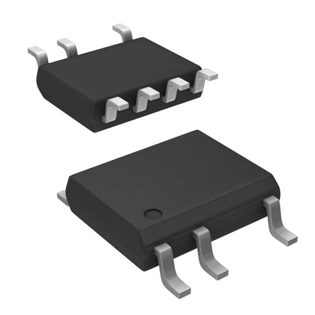
LNK304DN-TL Power Integrations
-
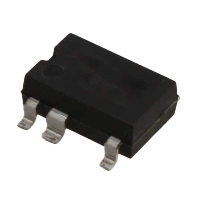
LNK304GN-TL Power Integrations
-
LNK304DG-TL Power Integrations
-
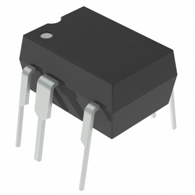
TNY277PN Power Integrations
-
TNY276PN Power Integrations
-
TNY278PN Power Integrations
-
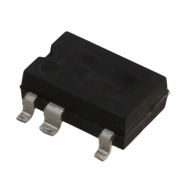
TNY278GN-TL Power Integrations
-
TNY280GN-TL Power Integrations
-
TOP266KG-TL Power Integrations
-
TOP258PN Power Integrations
-
TOP253PN Power Integrations
-
TOP253PNAU Power Integrations

- 1500+ Daily average RFQ Volume

- 20,000.000 Standard Product Unit

- 1800+ Worldwide Manufacturers

- 15,000+ In-stock Warehouse