


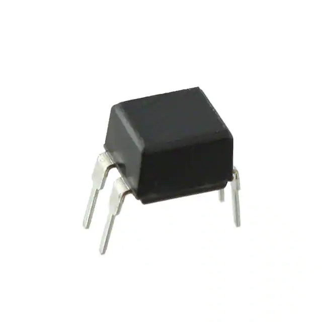
Sharp Microelectronics PC817

- Part No.:
- PC817
- Manufacturer:
- Sharp Microelectronics
- Package:
- 4-DIP (0.300", 7.62mm)
- Description:
- OPTOISOLATOR 5KV TRANS 4SMD
- Quantity:
-
Unit Price:$0
Ext Price:$0
- Payment:
-

- Shipping:
-


PC817 Information
- Specifications
- Product Details
- Comparison
- Tags
- Product attributes
- Attribute value
- Manufacturer:
- Sharp Microelectronics
- Series:
- -
- Package/Case:
- 4-DIP (0.300", 7.62mm)
- Packaging:
- Tube
- Product Status:
- Active
- Number of Channels:
- 1
- Voltage - Isolation:
- 5000Vrms
- Current Transfer Ratio (Min):
- 50% @ 5mA
- Current Transfer Ratio (Max):
- 600% @ 5mA
- Turn On / Turn Off Time (Typ):
- -
- Rise / Fall Time (Typ):
- 4µs, 3µs
- Input Type:
- DC
- Output Type:
- Transistor
- Voltage - Output (Max):
- 35V
- Current - Output / Channel:
- 50mA
- Voltage - Forward (Vf) (Typ):
- 1.2V
- Current - DC Forward (If) (Max):
- 60 mA
- Vce Saturation (Max):
- 200mV
- Grade:
- -
- Qualification:
- -
- Operating Temperature:
- -30°C ~ 100°C
- Mounting Type:
- Through Hole
- Supplier Device Package:
- 4-DIP
PC817 - 4-Pin DIP Phototransistor Optocoupler (5 kV Isolation)
The PC817 is a single-channel phototransistor-output optocoupler in a 4-pin DIP package. Input: an infrared LED. Output: an NPN phototransistor. Between them: 5,000 Vrms of galvanic isolation. It's the most common optocoupler in power supply feedback loops, microcontroller I/O isolation, and industrial signal isolation - and in the TL431 + PC817 pair, it forms the feedback path for practically every isolated flyback converter on the market.
Originally from Sharp, the PC817 is now manufactured by dozens of suppliers (EL817 from Everlight, LTV-817 from Lite-On, plus UMW, TGS, and others). The internal design has been stable for decades. The main thing that varies between manufacturers is the CTR binning and long-term reliability. The 4-pin DIP package fits a standard 2.54 mm pitch - socketable, breadboard-friendly, dead simple to rework.
It's not the fastest optocoupler (cutoff frequency ~80 kHz, rise/fall times ~4/3 μs at best), and it's not a linear device (the CTR curve is too nonlinear for precision analog). But for on/off isolation, level shifting, and the feedback loop in switching converters, it's the default answer. There's a reason it's been in every power supply textbook for 30 years.
What Is the PC817 and How Does It Work?
The PC817 has two sides separated by a transparent silicone isolation barrier. On the input side (pins 1 and 2), an infrared LED emits light when forward current flows. On the output side (pins 3 and 4), an NPN phototransistor converts that light back into current. The ratio of output collector current to input LED forward current is the Current Transfer Ratio (CTR) - expressed as a percentage.
The LED has a typical forward voltage of 1.2V at 20 mA. The phototransistor can handle up to 80V collector-emitter (on modern versions; original Sharp parts were 35V). The key to the PC817 is that there's no electrical connection between input and output - only photons cross the gap. That's what gives you the 5 kV isolation rating.
The PC817 is fundamentally an analog device: IC ≈ CTR × IF. But the CTR curve is nonlinear - it varies with IF, temperature, aging, and between individual units. That's why the PC817 is primarily used as a digital isolator (fully on or fully off) and not for precision analog signal transfer. For linear applications that need accurate signal reproduction across the isolation barrier, you'd use a dual-photodiode optocoupler like the IL300 or HCNR200.
What Are the Specifications of PC817?
| Parameter | Value | Notes |
|---|---|---|
| Isolation Voltage | 5,000 Vrms | Input to output, 1 minute |
| LED Forward Voltage (VF) | 1.2V typ, 1.4V max | At IF = 20 mA |
| LED Forward Current (IF) | 50 mA max continuous | Peak 1A (1 ms pulse) |
| Collector-Emitter Voltage (VCEO) | 80V max (modern); 35V (original Sharp) | Check your manufacturer's datasheet |
| Collector Current (IC) | 50 mA max | - |
| CTR Range | 50%–600% | Depends on rank grade |
| CTR Grade A | 80%–160% | General purpose |
| CTR Grade B | 130%–260% | Most common for SMPS feedback |
| CTR Grade C | 200%–400% | - |
| CTR Grade D | 300%–600% | - |
| VCE(sat) | 0.1V typ, 0.2V max | At IC = 2 mA, IF = 20 mA |
| Rise Time (tr) | 4 μs typ, 18 μs max | VCE = 2V, IC = 2 mA, RL = 100 Ω |
| Fall Time (tf) | 3 μs typ, 18 μs max | Same conditions |
| Cutoff Frequency (fC) | ~80 kHz | At -3 dB |
| Isolation Resistance | 5×10¹⁰ Ω typ | DC 500V, 40–60% RH |
| Operating Temperature | -30°C to +100°C | - |
| Package | DIP-4 (through-hole), SOP-4 (SMD) | 2.54 mm pitch, 4-pin |
Key Numbers That Matter
- CTR is not a constant: At IF = 5 mA and VCE = 5V, a PC817B gives you CTR between 130% and 260%. But change IF to 1 mA, and CTR drops sharply - the curve steepens below ~3 mA. Change temperature from 25°C to 85°C, and CTR can shift by ±30% depending on the LED material. From our experience, the #1 design mistake with the PC817 is assuming CTR is a fixed number. It's a range, and it moves with current, temperature, and age. If your circuit only works at one point on that curve, it will fail in production.
- CTR degradation over time: The LED in the PC817 loses quantum efficiency as it ages. Non-radiative recombination centers grow in the LED junction, and the encapsulant yellows, reducing light transmission. After several thousand hours at rated current, you can lose 10–30% of the initial CTR. From our experience, designs that operate the LED at 20 mA continuously (the datasheet max rating) see the fastest degradation. Running at 5–10 mA extends lifetime significantly. For products with a 10-year expected service life, design for at least 50% CTR margin above your minimum required value. If your feedback loop needs CTR ≥ 100% to regulate, specify a PC817B (130% min) so there's room for aging.
- Speed vs RL: The phototransistor's junction capacitance combined with the load resistor forms an RC low-pass filter. With RL = 10 kΩ, you get visible waveform rounding even at 2 kHz. With RL = 1 kΩ, the -3 dB bandwidth pushes past 80 kHz. From our experience, if you're doing PWM isolation at more than a few hundred Hz, keep RL in the 1–4.7 kΩ range. If you need sub-microsecond switching, use a logic-gate optocoupler like the 6N137 instead.
- VCE(sat) = 0.1V - but only at the right IF: The saturated VCE spec of 0.1V assumes IF = 20 mA and IC = 2 mA. If you're driving 10 mA on the output with only 5 mA through the LED (CTR = 200% minimum required), you may get VCE(sat) of 0.5V or higher. For a 3.3V system where every millivolt matters for logic thresholds, this is enough to cause problems. Check worst-case (minimum CTR, minimum IF, maximum IC), not typical.
What Is the PC817 Used For?
Switching Power Supply Feedback (With TL431)
This is the PC817's defining application. On the secondary side of an isolated flyback or forward converter, the TL431 senses VOUT and drives the PC817's LED. On the primary side, the phototransistor pulls the PWM controller's feedback pin, closing the loop across the isolation barrier. This two-chip solution - TL431 + PC817 - has been the industry standard for isolated power supply feedback since the 1980s. It replaces a costly magnetic feedback winding or a secondary-side controller with two commodity parts costing pennies each. From our experience, the vast majority of PC817s produced each year end up in this exact circuit.
Microcontroller I/O Isolation
Isolate a 3.3V or 5V MCU GPIO from a higher-voltage or noisy system. Drive the LED from the MCU pin through a current-limiting resistor (~220 Ω at 5V gives ~17 mA), and connect the phototransistor output to whatever you're controlling. Common in industrial PLC inputs, relay drivers, and interfacing with 12V/24V industrial logic.
Level Shifting
Shift a 3.3V logic signal to 5V, 12V, or 24V domains without a common ground. The output side can use whatever supply voltage you need (up to 80V VCEO), completely independent of the input side. No level-shifter IC required.
Zero-Crossing Detection (Mains)
With a capacitive dropper or high-value resistor network on the AC mains side, the PC817 LED turns on near the AC zero crossing, generating a pulse train on the output. This is the cheapest way to add zero-crossing detection to a microcontroller-based AC control system. From our experience, use at least a 100 kΩ series resistor (2W rated) from 220V AC, and add an anti-parallel diode across the LED to protect it from reverse voltage during the negative half-cycle.
Noise Isolation for Analog Front-Ends
Place a PC817 between a noisy digital board and a sensitive analog front-end. The galvanic isolation breaks ground loops that would otherwise couple digital switching noise into your analog measurements. For this application, the PC817 operates in its linear region - but keep in mind the nonlinear CTR. For precision analog isolation, use a dedicated linear optocoupler.
PC817 + TL431: The Power Supply Feedback Pair Explained
Since the PC817 and TL431 are almost always used together, it's worth understanding how they divide the work in a power supply feedback loop.
The TL431 does the thinking. It compares the output voltage (divided by R1/R2) against its internal 2.495V reference. The error between actual and desired output voltage determines how much current the TL431 sinks through its cathode.
The PC817 does the crossing. That TL431 cathode current flows through the PC817's internal LED. More TL431 current = brighter LED = more phototransistor current on the primary side. The PWM controller reads that current and adjusts the duty cycle.
The Rbias resistor is not optional. When the output voltage is exactly at the setpoint and the feedback loop is in steady state, the optocoupler LED current might be very low - possibly below the TL431's minimum 1 mA cathode current. Rbias (typically 1 kΩ from TL431 cathode to anode) provides a guaranteed current path so the TL431 never loses bias. From our experience, if your supply oscillates only at no-load or light-load conditions, Rbias is the first thing to check. Either it's missing, or the value is too high.
Match the CTR grade to the design. The TL431's cathode current range and the PWM controller's feedback pin current range together determine the required CTR. If you swap a PC817B (CTR 130–260%) for an ungraded PC817 (50–600%), the loop gain can change by a factor of 4. That's enough to turn a stable power supply into an oscillator. When repairing or respinning a design, always check what CTR grade the original BOM specified.
PC817 vs 4N35 vs 6N137: Which Optocoupler to Use
| Parameter | PC817 | 4N35 | 6N137 |
|---|---|---|---|
| Type | Phototransistor | Phototransistor + base pin | Logic gate with photodiode |
| Isolation Voltage | 5,000 Vrms | 3,550 Vrms (some 5kV) | 2,500 Vrms |
| CTR | 50%–600% | 20% min (at IF=10mA) | N/A (digital output) |
| Max Speed | ~80 kHz | ~10 kHz (with base resistor) | 10 MBd (10 Mbps) |
| VCEO | 80V (modern) | 30V | 7V (open-collector output) |
| Package | DIP-4 | DIP-6 | DIP-8 |
| Typical Use | PSU feedback, general isolation | Slow digital isolation | High-speed digital (MIDI, RS-485, CAN) |
| Cost | Lowest | Low | Medium |
Pick the PC817 when you need cheap, reliable isolation for analog feedback loops (SMPS), low-speed digital isolation (up to ~10 kHz), or level shifting - and you don't need sub-microsecond response.
Pick the 4N35 when you need access to the phototransistor base pin (for speed-up with a B-E resistor) and 10 kHz bandwidth is acceptable. The base pin lets you trade CTR for speed.
Pick the 6N137 when you need high-speed digital isolation (10 Mbps). It uses an internal photodiode + amplifier + logic gate, so there's no CTR to worry about - it outputs a clean TTL-level signal. Much faster, slightly more expensive.
Frequently Asked Questions About PC817
Q1: What is the PC817 used for?
A: Its primary application is the feedback path in isolated switching power supplies, paired with a TL431 shunt regulator. It's also widely used for microcontroller GPIO isolation, level shifting between voltage domains, relay driving, zero-crossing detection on AC mains, and general-purpose signal isolation up to about 10 kHz.
Q2: What does CTR mean and why does it matter?
A: CTR (Current Transfer Ratio) = IC / IF × 100%. It tells you how much output current you get for a given LED current. A PC817B with 200% CTR means 10 mA of LED current produces ~20 mA of collector current. CTR varies with forward current, temperature, and age - it's not a fixed number. In SMPS feedback loops, the CTR grade determines the loop gain, so swapping grades without adjusting compensation can cause oscillation.
Q3: Why is my PC817 output not switching properly?
A: Three most common causes: (1) LED forward current too low - below 3 mA the CTR curve steepens and the phototransistor may not saturate. Use at least 5 mA. (2) Load resistor too large - with 10 kΩ or more, the RC time constant with the phototransistor's junction capacitance rounds off edges and limits speed. Keep RL in the 1–4.7 kΩ range for switching applications. (3) Wrong output configuration - for switching, use common-emitter (load between collector and VCC). Common-collector (emitter follower) prevents saturation and gives poor logic levels.
Q4: Can I use PC817 to switch mains voltage (230V AC)?
A: No. The PC817's output transistor is rated for 80V DC max (35V on some versions). It cannot switch 230V AC directly. For mains switching, use a triac-output optocoupler like the MOC3041 or MOC3021, paired with an external triac rated for the load.
Q5: How fast can the PC817 switch?
A: With RL = 100 Ω, typical rise/fall times are 4/3 μs, giving a cutoff frequency around 80 kHz. In practice, with reasonable load resistors (1–4.7 kΩ), usable bandwidth is 10–50 kHz for clean digital signals. For PWM isolation above a few kHz, keep RL low. For sub-microsecond switching, use a high-speed logic-gate optocoupler like the 6N137.
Q6: Does the PC817 degrade over time?
A: Yes. The LED's quantum efficiency decreases with operating hours, and the internal encapsulant yellows, reducing light transmission. At rated current (20 mA continuous), expect 10–30% CTR loss after several thousand hours. From our experience, designs with a 10-year intended service life should budget at least 50% CTR margin above the circuit's minimum requirement. Running the LED at 5–10 mA instead of 20 mA significantly extends lifetime.
Q7: Can I replace PC817 with EL817 or LTV-817?
A: Yes, in most cases. EL817 (Everlight) and LTV-817 (Lite-On) are functionally equivalent second-sources. The key thing to check is the CTR grade - make sure the replacement has the same or compatible CTR range (A/B/C/D). In power supply feedback loops, changing the CTR grade without verifying loop stability is a common source of post-repair oscillation. If the original BOM specified PC817B (CTR 130–260%), replace with the same grade from any manufacturer.
Q8: Why does my PC817 have 4 pins but the datasheet shows a 4-pin package?
A: The standard PC817 has exactly 4 pins: pin 1 (Anode), pin 2 (Cathode) on the input side, pin 3 (Emitter), pin 4 (Collector) on the output side. Pin numbering is read counterclockwise from the dot/notch on top, looking from above. Some variants (PC817X series) come in SOP-4 surface-mount packages - same pinout, different footprint.
Pricing & Availability
| Parameter | Details |
|---|---|
| Part Number | PC817 (Sharp / multi-source) |
| Equivalents | EL817 (Everlight), LTV-817 (Lite-On), 817 (UMW/TGS) |
| Package | DIP-4 (through-hole), SOP-4 (SMD) |
| CTR Grades | A (80–160%), B (130–260%), C (200–400%), D (300–600%) |
| Condition | New, original manufacturer |
| Lead Time | In stock, ship from Shenzhen |
Contact ICMASS for current pricing on PC817 and compatible alternatives (EL817, LTV-817). We stock multiple CTR grades with full traceability. The PC817 and TL431 are available as a companion pair for power supply feedback designs - order both together for matched CTR grading in production quantities.
| Image |
|
|
|
|
|
| Part Number | PC817XJ0000F | PC817X1J000F | PC817X2J000F | PC817X4J000F | PC817X |
| Manufacturer | Sharp Microelectronics | Sharp Microelectronics | Sharp Microelectronics | Sharp Microelectronics | Sharp Microelectronics |
| Series | - | - | - | - | - |
| Package/Case | 4-DIP (0.300", 7.62mm) | 4-DIP (0.300", 7.62mm) | 4-DIP (0.300", 7.62mm) | 4-DIP (0.300", 7.62mm) | 4-DIP (0.300", 7.62mm) |
| Packaging | Tube | Tube | Tube | Tube | Tube |
| Product Status | Obsolete | Obsolete | Obsolete | Obsolete | Obsolete |
| Number of Channels | 1 | 1 | 1 | 1 | 1 |
| Voltage - Isolation | 5000Vrms | 5000Vrms | 5000Vrms | 5000Vrms | 5000Vrms |
| Current Transfer Ratio (Min) | 50% @ 5mA | 80% @ 5mA | 130% @ 5mA | 300% @ 5mA | 50% @ 5mA |
| Current Transfer Ratio (Max) | 600% @ 5mA | 160% @ 5mA | 230% @ 5mA | 600% @ 5mA | 600% @ 5mA |
| Turn On / Turn Off Time (Typ) | - | - | - | - | - |
| Rise / Fall Time (Typ) | 4µs, 3µs | 4µs, 3µs | 4µs, 3µs | 4µs, 3µs | 4µs, 3µs |
| Input Type | DC | DC | DC | DC | DC |
| Output Type | Transistor | Transistor | Transistor | Transistor | Transistor |
| Voltage - Output (Max) | 80V | 80V | 80V | 80V | 80V |
| Current - Output / Channel | 50mA | 50mA | 50mA | 50mA | 50mA |
| Voltage - Forward (Vf) (Typ) | 1.2V | 1.2V | 1.2V | 1.2V | 1.2V |
| Current - DC Forward (If) (Max) | 50 mA | 50 mA | 50 mA | 50 mA | 50 mA |
| Vce Saturation (Max) | 200mV | 200mV | 200mV | 200mV | 200mV |
| Grade | - | - | - | - | - |
| Qualification | - | - | - | - | - |
| Operating Temperature | -30°C ~ 100°C | -30°C ~ 100°C | -30°C ~ 100°C | -30°C ~ 100°C | -30°C ~ 100°C |
| Mounting Type | Through Hole | Through Hole | Through Hole | Through Hole | Through Hole |
| Supplier Device Package | 4-DIP | 4-DIP | 4-DIP | 4-DIP | 4-DIP |
User Guide
- Purchase & Inquiry
- Package
- Shipping Information
- Customer Review
You may place an order without registering to IC-MAX.COM
We strongly suggest you sign in before purchasing as you can track your order in real time.
For your convenience, we accept multiple payment methods in USD, including PayPal, Credit Card, and wire transfer.
RFQ (Request for Quotations)
It is recommended to request for quotations to get the latest prices and inventories about the part.
Our sales will reply to your request by email within 24 hours.
1. You'll receive an order information email in your inbox. (Please remember to check the spam folder if you didn't hear from us).
2. Since inventories and prices may fluctuate to some extent, the sales manager is going to reconfirm the order and let you know if there are any updates.
-

- Step1:Prepare product
-

- Step2:Vacuum packaging
-

- Step3:Anti-static bag
-

- Step4:Individual package
-

- Step5:Packaging box
-

- Step6:Barcode shipping label
Shipping starts at $40, but some countries will exceed $40. For example (South Africa, Brazil, India, Pakistan, Israel, etc.)
The basic freight (for package ≤0.5kg or corresponding volume) depends on the time zone and country.
Currently, our products are shipped through DHL, FedEx, SF, and UPS.
Delivery TimeOnce the goods are shipped, estimated delivery time depends on the shipping methods you chose:
FedEx International, 5-7 business days.
The following are some common countries' logistic time.

- Hot Sale
- Related Categories
- Include Parts
- Popular Search
The following parts include "PC817" in Silicon Labs PC817.
- Part Number
- Manufacturer
- Package
- Description
- LTV-816S Lite-On Inc. 4-DIP (0.300", 7.62mm) OPTOISOLATOR 5KV TRANS 4SMD
- CNY17-3 Vishay Semiconductor Opto Division 4-DIP (0.300", 7.62mm) OPTOISOLATOR 5KV TRANS 4SMD
- LTV-816S-TA1 Lite-On Inc. 4-DIP (0.300", 7.62mm) OPTOISOLATOR 5KV TRANS 4SMD
- LTV-817 Lite-On Inc. 4-DIP (0.300", 7.62mm) OPTOISOLATOR 5KV TRANS 4SMD
- LTV-817S Lite-On Inc. 4-DIP (0.300", 7.62mm) OPTOISOLATOR 5KV TRANS 4SMD
- LTV-817S-TA1 Lite-On Inc. 4-DIP (0.300", 7.62mm) OPTOISOLATOR 5KV TRANS 4SMD
- LTV-826S Lite-On Inc. 4-DIP (0.300", 7.62mm) OPTOISOLATOR 5KV TRANS 4SMD
- FOD817CSD onsemi 4-DIP (0.300", 7.62mm) OPTOISOLATOR 5KV TRANS 4SMD
- LTV-356T Lite-On Inc. 4-DIP (0.300", 7.62mm) OPTOISOLATOR 5KV TRANS 4SMD
- LTV-357T Lite-On Inc. 4-DIP (0.300", 7.62mm) OPTOISOLATOR 5KV TRANS 4SMD
The following parts are popular search parts in Test and Measurement.
Inventory:0
Please send an inquiry. Send us your inquiry, and we will respond immediately.

- 1500+ Daily average RFQ Volume

- 20,000.000 Standard Product Unit

- 1800+ Worldwide Manufacturers

- 15,000+ In-stock Warehouse


